
Accelerometers Versus Velocity Sensors – What's the Difference?
To determine whether you should use an accelerometer or velocity sensor, it is first important to understand the difference between them. An accelerometer is a mechanical device used to measure the change in motion or acceleration of a structure or machine. This motion is then converted into an electrical signal that can be measured. Often an accelerometer can be used to measure the force of impact, or the vibration of a machine. These devices can help ensure your machinery is working correctly.
Instead of measuring an absolute position, a velocity sensor uses a seismic device to measure changing positions over time. Then it calculates this change to determine the velocity.
To better determine which form of measurement is most ideal for your specific situation, read the following steps to determine whether you should use an accelerometer or a velocity sensor.
Step 1: Determine what you want to measure
The general rules of thumb are as follows:
If the rotor can move relative to the casing, and you are interested in actual shaft motion, you must use a proximity probe.
- If you are interested in casing motion, you should use a seismic transducer (velocity sensor or accelerometer); your choice of which to use should be governed by considering the signal strength the transducer will provide at the frequency(ies) of interest.
- If you choose an accelerometer for certain applications, the signal strength can be very small (less than a few millivolts) and can easily be swamped by the noise in the system, making it hard to separate signal from noise.
- Although a piezo-velocity sensor is just an accel with an internal integrator, it gives superior results to integration in the monitor. This again is because of signal strength (in mV) coming out of the sensor relative to the strength of the noise (in mV).
- A piezo-velocity sensor is usually a good choice at low and medium rotative speeds; an accel is usually a poor choice at low rotative speeds, but a good choice at medium and high rotative speeds.
Remember for a fluid film bearing machines you generally want to use shaft observing proximity probes, an exception is for reciprocating machines. Even though the reciprocating machines have fluid film bearings supporting the crankshaft, the machines are so stiff there is little to no relative motion between the crankshaft and the casing, so casing mounted transducers would be a better application in this case. For rolling element bearing machines, there is very little relative motion between the rotor and the casing, so casing-mounted transducers are usually the best application. An exception is for slow-moving rotors that have very large rolling element bearings; in this case, a proximity probe may be the best sensor for machine conditions due to the slow shaft motion and the possibility of rolling-element bearing wear.
Step 2: Determine the frequencies of interest
- Most rotor-related malfunctions (unbalance, misalignment, metal to metal rubs, instability, shaft cracks, cage flaws, etc.) appear between 1/4X to 3X (1X = rotor speed, measured in revolutions per minute (rpm), cps, or Hz).
- Most rolling-element bearing defects occur in the region of 1 to 6 times the Ball Pass Frequency Outer Race (simply put BPFO ~ #Elements x RPM / (2 x 60sec/min) = Y cps, or Y Hz).
- Higher vibration frequencies may be a result of blade passage rate, gear mesh, harmonics of BPFO frequency, and other vibration harmonics (blade passage rate = # blades x rotor speed (1X), gear mesh frequency = # gear teeth x rotor speed (1X), harmonics are multiples of the fundamental forcing frequencies generated when the vibration waveform is not a perfect sine wave).
- Impact events are a source of broadband energy that excites higher-order frequencies.
Example: A centrifugal pump, with a seven blade impeller, operating at 3000 rpm, with rolling element bearings, with 10 rolling elements per bearings needs monitoring. The frequencies of interest are:
1X = 3000 rpm = 50 cps = 50 Hz
1/4X to 3X = 12.5 to 150 cps = 12.5 to 150 Hz, for rotor related malfunctions
BPFO approximately = 10 elements x 50 cps / 2 = 250 cps = 250 Hz
1 to 6 times the BPFO = 250 to 1500 cps = 250 to 1500 Hz, for bearing related malfunctions
Blade Passage Rate = 7 x 50 cps = 350 cps = 350 Hz
One would select a casing-mounted transducer that could measure at least 12.5 Hz to 1500 Hz.
Step 3: Determine the required casing
In general, acceleration is large at high frequencies and small at low frequencies. Displacement is just the opposite: small at high frequencies and large at low frequencies. Velocity tends to be more constant at different frequencies. The graph below shows the relationship of displacement and acceleration when velocity is held constant while varying the frequency range.
For this graph to have meaning in terms of signal strength, we have to add in the transducer sensitivity. Normally, vibration transducers have the following sensitivities:
- Velocity = 100mV/in/sec = 3.94 mV/mm/sec
- Acceleration = 100 mV/g
- Displacement = 200 mV/mil = 7.87 mV/µm
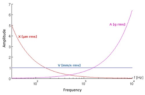
Also, notice that in the above graph the units are in rms (root mean squared); rms is a measure of the average power of the vibration signal (mathematically, for a sine wave with a peak amplitude of A, the rms amplitude is A/ ).
The table below shows a constant value of the velocity at 0.5 in/s (12.7 mm/s) at various frequencies:
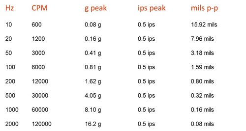
For the examples below, let’s assume a constant velocity (0.5 in/s) at 600 rpm, 3000 rpm, and 30,000 rpm to illustrate the differences.
Example 1: 600 rpm
Assume we have a machine running at very low speeds (say, 600 rpm) with 0.5 in/s pk of vibration.
Displacement @ 600 rpm: 15.92 mils pp at 200 mV/mil from a standard proximity probe this gives a signal of 3184 mV (15.92 mils pp x 200 mV/mil = 3184 mV = 3.134 Volts).
Acceleration @ 600 rpm: 0.08 g pk at 100 mV/g from a standard accel this gives a signal of 8.0 mV (0.08 g pk x 100 mV/g = 8.0 mV = 0.008 Volts).
Velocity @ 600 rpm: 0.5 in/s pk at 100 mV/ips* from a standard piezo-velocity sensor this gives a signal of 50 mV (0.5 in/s pk x 100 mV/ips = 50 mV = 0.05 Volts). *in/sec = ips
Here, we see that displacement gives a huge signal (3184 mV), velocity gives a moderate signal (50 mV) and acceleration gives a very small signal (8 mV). The signal strength in mV is approximately 6 times better for velocity than for acceleration.
Example 2: 3000 rpm
This is for a medium-speed machine at 3000 rpm…
Displacement @ 3000 rpm: 3.18 mils pp at 200 mV/mil from a standard proximity probe gives a signal of 636 mV.
Acceleration @ 3000 rpm: 0.41 g pk at 100 mV/g from a standard accel this gives a signal of 41 mV.
Velocity @ 3000 rpm: 0.5 in/s pk at 100 mV/ips* from a standard piezo-velocity sensor this gives a signal of 50 mV.
*in/sec = ips
Here, we see the signal strength in mV is moderate for both the velocity and for the acceleration transducer.
Example 3: 30,000 rpm
Now let’s do the same thing for a machine running at high speed (30,000 rpm)…
Displacement @ 30000 rpm: 0.32 mils pp at 200 mV/mil from a standard prox probe gives a signal of 64 mV. Acceleration @ 30000 rpm: 4.05 g pk at 100 mV/g from a standard accel this gives a signal of 405 mV. Velocity @ 30000 rpm: 0.5 in/s pk at 100 mV/ips* from a standard piezo-velocity sensor this gives a signal of 50 mV *in/sec = ips
Here, we see that acceleration gives a very strong signal, velocity a moderate signal, and displacement a moderate signal.
Step 4: Consider the environment the transducer will be in
The transducer selected needs to be able to accurately measure the environment it is installed in. Pay attention to the temperature and humidity constraints. Is the transducer going to be submerged? Are hazardous area approvals needed?
Step 5: Choose the right transducer
After considering the machine type, the bearing type, the frequencies of interest, the transducer sensitivity for the signals you are measuring, and the environment you are ready to make a transducer selection.
For machines with rolling element bearings, rotating at 1500 to 3600 rpm, velocity sensors have proven to be a very effective condition monitoring tool.
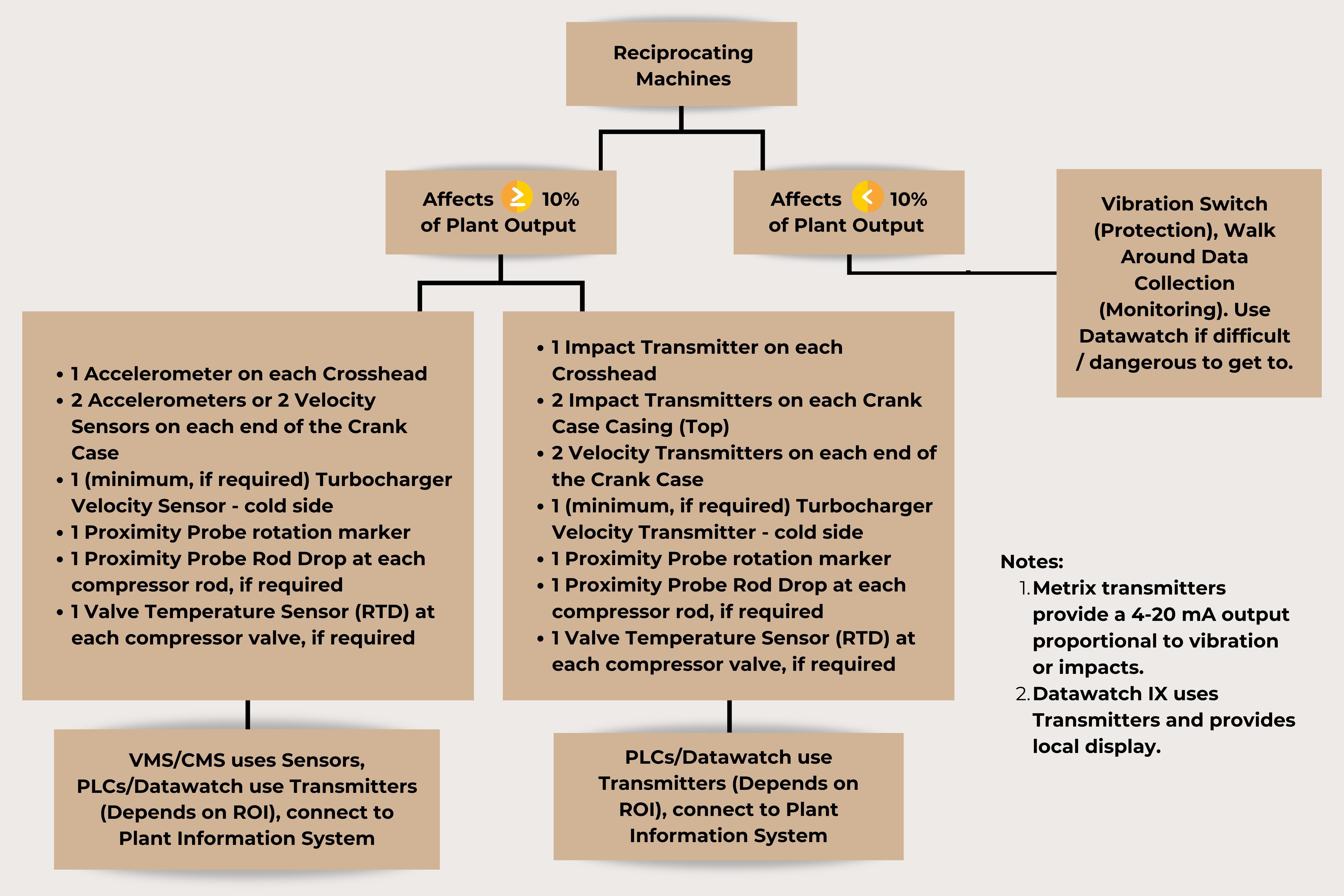
For reciprocating machines, with their ability to transmit vibration from the crankcase to the casing, and due to their lower speeds, velocity is the best measure of overall vibration severity and machine condition. Due to possible impact events (valves, crankshaft, crosshead, etc.) impact measurement (via an impact transmitter or accelerometer connected to an appropriate monitor) is also an indicator of machine condition.
Step 6: Economic Considerations
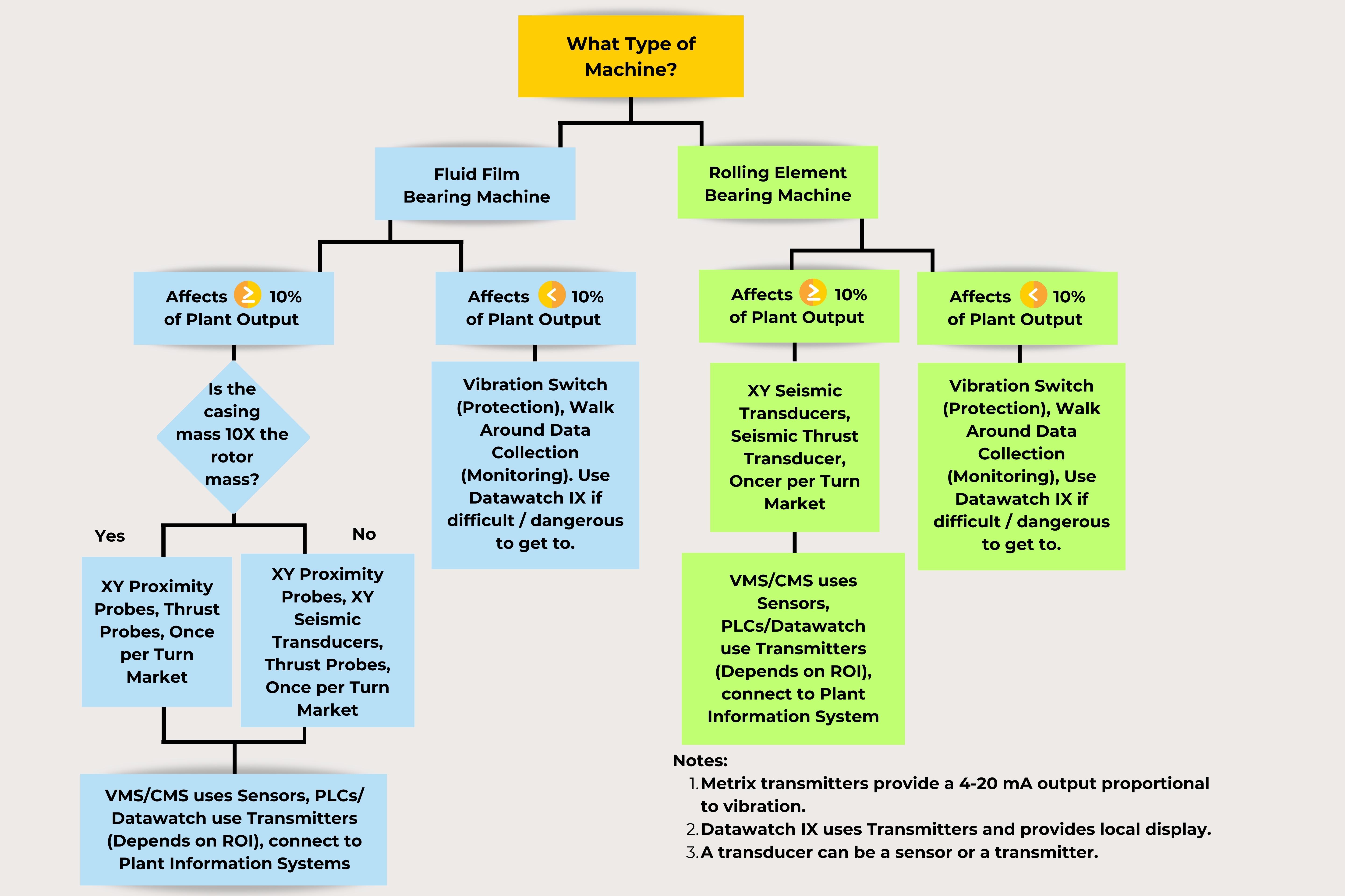
The choice between a seismic sensor, a seismic transmitter, or the use of a vibration switch depends upon the Return on Investment (ROI) the customer equates with the risk of personnel safety, repair costs, and unscheduled downtime resulting in Lost Opportunity Cost (LOC) the rotating or reciprocating machine may affect. A more thorough discussion of economic considerations is found in the application whitepaper “Metrix Vibration Monitoring Methodology.” The following charts are useful in determining what type of vibration sensor, transmitter or switch should be used.
If you have additional questions regarding vibration measuring systems, please contact Metrix Vibration today.