
Q & A for Proximity Devices Whitepaper
- What is Cross Talk, when do you have to worry about it, and how do you eliminate it?
- What is the Invert Buffered Output Polarity used for?
- When would one enable Spike Suppression?
- How do you change the units to Metric for verification and reports?
- What does Thrust Direction Upscale mean?
- What is Threshold and Hysteresis used for when using the MX2034 as a Speed Transmitter?
- How does one change the Target Material for DPS 1.35?
- How does DPS 1.35 Handle Unknown Target Materials?
- How are changes in System Length allowed for DPS 1.35 proximity probe systems?
- How does one change the Full Scale Range for the DPS 1.35?
- How is the proximity system "Verification" done with the DPS 1.35?
- How is a Custom Calibration of the DPS 1.35 conducted?
- How does one Generate a Report using the DPS 1.35 Software?
- How does material type impact proximity readings?
- Is the Metrix Digital Proximity System, the MX2033 Driver or MX2034 Transmitter, as good as an analog driver or transmitter from our competitors?
- How does the Metrix MX2033 Driver / MX8030 Probe System compare to an Analog Probe System?
- How compatible is the Metrix DPS with Bently Probes and Cables?
- How flexible is the Metrix Digital Proximity System compared to an Analog System?
- How does the Metrix TIGHTVIEW® application work versus a Narrow Side View product?
- Do we need to select the TIGHTVIEW® option to reach BN NSv performance? *NEW*
- What is the advantage of the Metrix MX Series over the BN NSv proximity system in Tight Situations? *NEW*
- Is the Metrix MX Series compatible with the BN NSv proximity system? *NEW*
-
What is Cross Talk, when do you have to worry about it, and how do you eliminate it?
Cross Talk Elimination is used when proximity probes are close together, typically less than 25mm. This DPS 1.35 feature is used on one of the probes that could interfere electrically with another probe close by. This feature can be used on an MX2033 Driver or MX2034 Transmitter proximity probe system. This feature shifts the oscillation frequency of the DPS unit so it is different from the adjacent probe, thereby, preventing Cross Talk interference. Do not use this feature on both probes that are close by, if you do you will continue to have a Cross Talk problem albeit at a different frequency. Only use Cross Talk Elimination on one of the probes of the set.
If you request Cross Talk Elimination on one of the two adjacent DPS units when you order DPS system from Metrix, the pair you receive from our manufacture will have label "X" and "Y" respectively. The standard DPS unit has no label for Cross Talk and it is default to "X". However, if you experience Cross Talk in your application you can convert one of the two adjacent DPS units to "Y" configuration in the field through the Advanced Settings page in the "Metrix DPS Configuration and Utility Software". Please refer to the DPS 1.35 Software Installation Manual for more information.
In close proximity probe applications, the Metrix DPS can be calibrated with a different driving frequency that allows the probes to be within 12.5 mm (0.5 inches) of each other, and not interfere with each other probe’s signal. This is perfect for the Air Machine market, due to the small 25 mm (1 inch) shafts typical of these machines. Competitor probes have to be at least 37mm (1.5 inches) apart to measure properly. Please let the Metrix factory know when you have a close XY probe pair (close is less than 25 mm (1 inch)).
-
What is the Invert Buffered Output Polarity used for?
Using the DPS 1.35 some customers want a positive output from the BNC of the MX2034 transmitter. Normal polarity is negative for output at the BNC of the MX2034 Transmitter, this feature allows the user to change the output polarity to positive. This feature is only applicable to the MX2034 Transmitter.
This feature can be accessible through the Advanced Settings page in "Metrix DPS Configuration and Utility Software". Please refer to the DPS 1.35 Software Installation Manual for more information. -
When would one enable Spike Suppression?
Using a MX2034 Transmitter, this DPS 1.35 feature is used to inhibit high amplitude electrical noise from outside the vibration monitoring system from impacting the performance of the vibration transmitter system.
- This feature temporarily suppresses high amplitude, short duration, typically less than 50 millisecond vibration spikes - like those induced possibly by a portable radio when keying the mic.
- If this feature is selected, any vibration spike greater than the full-scale range (default), or lesser value selected by the user, will be suppressed for the default duration of 1 milliseconds or the time duration selected by the user up to 1000 milliseconds (1 second).
- During a Spike Suppression event, the output of the vibration transmitter will go to 3.0mA for approximately 0.25 seconds to inform the Control System that a Spike Suppression event has occurred.
- Vibration amplitudes greater than the Spike Suppression setting, that last longer than the Spike duration setting, will be reported normally via the 4-20 mA output.
- The dynamic output via the BNC, on the transmitter, is not impacted by enabling Spike Suppression.
This feature can be accessible through the Advanced Settings page in "Metrix DPS Configuration and Utility Software". Please refer to the DPS 1.35 Software Installation Manual for more information.
-
How do you change the units to Metric for verification and reports?
Go to the "Advanced Settings" tab and select "Metric", the units for the table and plots on the "Verification" tab are now in Metric Units. Note: This does not change the configuration of the transducer, that is changed on the "Home" tab. This feature works for both the MX2033 Driver and MX2034 Transmitter. It can be accessible in the Advanced Settings page in "Metrix DPS Configuration and Utility Software". Please refer to the DPS 1.35 Software Installation Manual for more information.
-
What does Thrust Direction Upscale mean?
For the DPS MX2034 Transmitter the "Upscale" selection will correlate the low value of the full-scale range with the 4mA output of the transmitter, and the 20mA output at the high value of the full-scale range. The "Downscale" selection will correlate the high value of the full-scale range with the 4mA output of the transmitter, and the 20mA output at the low value of the full-scale range. This can be useful for the operator, the control system or display device. This feature can be accessible through the Advanced Settings page in "Metrix DPS Configuration and Utility Software". Please refer to the DPS 1.35 Software Installation Manual for more information.
-
What is Threshold and Hysteresis used for when using the MX2034 as a Speed Transmitter?
This DPS 1.35 feature for the MX2034 Transmitter is used to improve the performance of the speed measuring system.
- Auto - allows one to use an Auto Threshold setting, which will trigger the DPS with a large negative pulse (> -6Vdc).
- Manual - Threshold setting allows the user to select the threshold value (usually -13 Vdc or greater) and a hysteresis band of up to +/- 2.5 Vdc for a negative going pulse.
- One must insure the negative going pulse will produce a more negative voltage than the hysteresis dead band. Hysteresis creates a dead band around the threshold value.
- For example, assume the initial gap voltage is set to -10 Vdc, if the Threshold was set at -13 Vdc, and the Hysteresis was set at +/- 1.0 Vdc, the negative going pulse would have to pass -14 Vdc (-14Vdc = -13Vdc -1Vdc) to have counter within the transmitter see the pulse, and then the counter would not reset until it saw the voltage pass through -12 Vdc (12Vdc = -13Vdc + 1Vdc) on its way back to the original gap voltage. Also note: If the initial gap is set to -10 Vdc, and the threshold is Manually set to <-10 Vdc the system will not work because the negative going pulse is always exceeded. This gets extended to the Hysteresis dead band, it must always be more negative than the initial gap voltage (e.g. -10 Vdc is gap voltage, then dead band of -12 Vdc to -14 Vdc is okay).
- Using Threshold and Hysteresis are great ways to help reduce noise and increase accuracy in a speed measurement system.
This feature can be accessible through the Advanced Settings page in "Metrix DPS Configuration and Utility Software". Please refer to the DPS 1.35 Software Installation Manual for more information.
-
How does one change the Target Material for DPS 1.35?
Using Metrix DPS Configuration and Utility Software, the "Change Configuration" menu option on the "Home" page tab allows one to change the target material from AISI 4140 Carbon Steel to another shaft material. Only Metrix Probe Series MX8030 and MX2030 allows the user to change to the other available materials listed. The materials listed represented 95% of the material types ever ordered from Metrix. All other probe types only have AISI 4140 as the Target Material in our standard delivery. If you have special Target Material other than AISI 4140 and request Probe Series other than MX8030 and MX2030, please contact our customer service.
-
How does DPS 1.35 Handle Unknown Target Materials?
While connected to a DPS Unit, using Metrix DPS Configuration and Utility Software, the "Unknown Material Calibration" tab functions allow the DPS Proximity Probe System be calibrated to an unknown target material using this process:
- Take advantage of the Metrix 9060-SCDM (Shaft Calibrator Dial Micrometer - for 5mm/8mm probes, with 4 inch (100mm) probe bodies or less) or the 9060-SCTS (Shaft Calibrator Touch Select - for 5mm/8mm/11mm probes including probe holders, with 2.5 inch (75mm) probe bodies or greater) to calibrate the Metrix DPS with the unknown shaft material.
- These systems allow one to take data directly on the shaft target material.
- Unknown Target Materials result in a trial and error process. For the first iteration, use AISI 4140 Carbon Steel material type. If the verification check is running cold (< 200 mV/mil or 7.87 mV/μm for IFS) then a custom calibration should be effective. If the verification is running hot, and exceeds 19Vdc, try a less dense material like one of the stainless steels.
-
How are changes in System Length allowed for DPS 1.35 proximity probe systems?
Using Metrix DPS Configuration and Utility Software, "Change Configuration" menu option on the "Home" page tab allows one to change the System Length of a DPS. This DPS 1.35 feature allows the user to switch between standard system lengths for the Probe Series selected:
The Metrix 7200 and BN 3300XL has 5 and 9 meter System Lengths listed only. The 3000 Series probes only have 15 feet and 20 feet listed.
The Metrix MX8030 and MX2030 Probe Series allow the DPS to take advantage of extended Systems Lengths from 1 to 12 meters for Vibration and Thrust, and to 20 meters for Speed measurements. If a user wants to use a length other than listed, like 7.6 meters, the user would use a 7 meter or an 8 meter System Length and perform a verification check to determine which length provided the best results. If the verification is not within limits a Custom Calibration can be conducted using the Verification Voltage values.
Users can use the Metrix MX8020-001 Cable Trimming and Connector Kit to alter the length of a MX8030 probe or MX8031 extension cable. Users no longer have to keep coils of extension cable in their junction boxes.
-
How does one change the Full Scale Range for the DPS 1.35?
Using Metrix DPS Configuration and Utility Software, the "Change Configuration" menu option on the "Home" page tab allows one to change the MX2034 Transmitter Full Scale Range. This feature is dependent upon what is selected for the MX2034 Transmitter measurement. The MX2033 Driver output goes to a monitoring system, so the Full Scale Range is not used. If the Transmitter Measurement was:
- Position then the 4 to 20mA scale can be selected for the appropriate displacement output, either in mils or microns (μm).
- Vibration then the 4 to 20mA scale can be selected for the appropriate vibration output, either in mils pk-pk (peak to peak) or microns pk-pk.
- Speed then the 4 to 20mA scale can be selected for the appropriate speed output in rpm (revolutions per minute).
-
How is the proximity system "Verification" done with the DPS 1.35?
Using the Metrix DPS Configuration and Utility Software, connected to a DPS Unit, while using the "Verification" tab the DPS Proximity Probe System can be verified to a known target material using this process:
This process can be completed by using a Proximity Probe static calibrator (dial micrometer) looking at shaft target material or the shaft directly.
- When the proper gap is set between the probe and appropriate target material in 10 mil or 250 micron increments, use the "Get" button for the DPS to gather the voltage information.
- Please note that this process takes between 5 and 10 seconds, and cannot be filled in. It must be the voltage measured by the Metrix Digital Proximity System 1.35.
- As the gaps are changed and voltages recorded the system draws the line between points, calculates the Incremental Scale Factor (IFS - slope between points), the Average Scale Factor (ASF) and the Deviation from Straight Line (DSL - 1 mil or 25 μm).
- Acceptable IFS for a 200 mV/mil Proximity Probe is from 190 to 210 mV/mil or 7.48 to 8.26 mV/μm (200mV/mil + 5% or 7.87mV/μm + 5%, per API 670).
-
How is a Custom Calibration of the DPS 1.35 conducted?This will use the results measured in the Verification Step to create a Custom Calibration for the DPS unit connected.
If the results of a "Verification" are unsatisfactory, then using the Metrix DPS Configuration and Utility Software, and using the voltages recorded after a "Verification" the user can select "Perform a Custom Calibration - Yes".
- To ensure the Custom Calibration was effective perform the Verification step again.
- If the Verification after the Custom Calibration is not satisfactory, you can try it again. If the results are still unsatisfactory, it is recommended to change parameters like System Length, or Material Type as appropriate.
- It could also be a problem with the system set up or some component of the system such as probe, cable or DPS unit.
- Please note - that last point (100 mils or 2500 μm) is not required, Metrix put this in because we normally can meet this distance. The API requirement is 80 mils (2250 μm) of linearity.
-
How does one Generate a Report using the DPS 1.35 Software?
Using the Metrix DPS Configuration and Utility Software, connected to a DPS Unit, while using the "Verification" tab the DPS Proximity Probe System verification can be used to produce a Verification report in Excel. With data in the Verification Table the user selects "Generate Report". The system will prompt the user to input appropriate information for the test.
- None of the fields are required, but are usually necessary for proper documentation.
- The data from the DPS Configuration is automatically uploaded into the report.
- After the report fields are filled in, or not, the user selects "OK" and then the user is prompted to input a file name and file location. The file generated is a Microsoft Excel file.
- Upon opening the Excel file the header and footer can be changed, and the file can be supplemented with other verifications.
- Other verifications can be added, using the Excel copy and paste feature, to create a complete report.
-
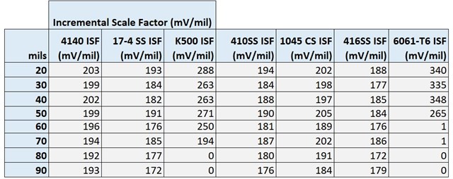
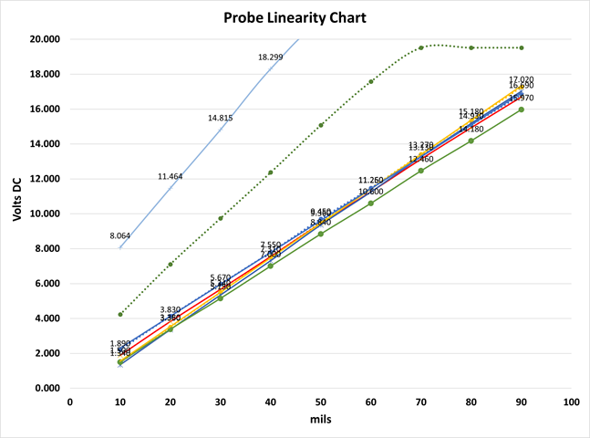
How does material type impact Proximity Readings?
The Proximity system generates eddy currents in the surface of the material. Depending on the range of the probe to the target material, the voltage output will be impacted by the eddy currents. The eddy currents generated in the target material are impacted by the material density, surface roughness and composition, and electromagnetic properties of the elements contained in the material. In the data below, Metrix used the same probe and cable and DPS unit to generate the curves. You will notice that the 6061-T6 Aluminum and K500 Monel materials perform differently as compared to the other materials tested (e.g. 4140 Carbon Steel, 410 Stainless Steel, etc.).
These material differences are why Metrix allows DPS users to perform custom calibrations.
The DPS can accommodate differences in material, system length and probe type. All of these materials below could have been ordered directly from the factory or custom calibrated in the field to be within the API 670 specifications of 200 mV/mil +/- 5% (7.87 mV/μm).
-
Is the Metrix Digital Proximity System, the MX2033 Driver or MX2034 Transmitter, as good as an analog driver or transmitter from our competitors?
This question is complex in that it has two answers, one regarding amplitude resolution and the other regarding frequency resolution. Both are discussed below.
What is the amplitude resolution of the Metrix DPS MX2033/MX2034?
0.012 mils (0.47 μm) The DPS driver / transmitter uses 16-bit resolution. Due to noise we remove 2 bits of resolution, leaving 14 bits between 1 volt and 19.0 volts. This gives us 0.012 mils/division of resolution (2^14 = 16384 divisions of resolution. 18.0 volts for 90 mils = 200 mV/mil. 18 V / 16384 divisions = 0.0011 V/div = 1.1 mV/div, which equates to a resolution of 0.012 mils/division (0.012 mils/division = 1.1 mV/div / 200 mV/mil).
What is the resolution of an analog device?
Usually, most literature states "the proximity probe is highly accurate," however, what does that mean? One must understand that a proximity probe uses a high frequency radio carrier wave (~ 1MHz) that is modulated by the change in gap voltage. The modulated frequency is filtered from the carrier radio wave frequency, and this becomes the gap and vibration signal. This modulation and demodulation within the analog processing circuit has limits. This results in an amplitude resolution, or accuracy, of 0.1 mils for a typical 5 or 8mm analog proximity system (see Orbit Magazine Article "Bently Nevada™ dual Probe versus Shaft Rider" February 12th, 2015. The Metrix DPS can resolve 0.012 mils - it is almost 10X more accurate than an analog system.
What is the frequency resolution of the DPS driver (MX2033), and buffered output of the DPS transmitter (MX2034)?
The DPS samples at a rate of 18kHz. That means that a 1 Hz (1 cycle per second) vibration signal will be sampled 18,000 times, during that second. Let's use a more practical example, let's say the machine operates at 3000 rpm, and it has one cycle of vibration for every rotation of the rotor; this is called 1X vibration. The 1X vibration is 3000 cycles per minute, or 50 Hz (50 cycles per second). With our DPS, the vibration signal is sampled 360 times for each vibration cycle (18,000 samples per second / 50 cycles per second = 360 samples per cycle). At this frequency, we get an excellent picture of the vibration waveform. Even with our high sample rate we have limits for the highest frequency of interest we can sample for, and that is called the Nyquist Frequency. The basic principle behind the Nyquist Frequency is that one has to sample at least two times during the vibration cycle to discretely determine the frequency of interest. The Nyquist Frequency for the DPS is 9 kHz (18,000 / 2 = 9000 Hz), which is quite excellent considering most machinery vibrations of interest are in the 1/4X to 3X vibration range. Also, note that the amplitude rolls off (decreases) at 16 kHz, so we can reliably detect frequencies up to 8 kHz (16 kHz / 2 = 8 kHz). For example; let's take an extreme case of a machine that operates at 100,000 rpm (1X = 100,000 cpm = 1667 cycles per second = 1667 Hz - Keep in mind most machines operate less than 10,000 rpm). The frequencies of interest for this 100,000 rpm (1667 Hz) machine are 416 Hz (0.25 x 1667 Hz) to 5001 Hz (3 x 1667 Hz), well within the DPS Nyquist Frequency range.
What is the frequency response of an analog device?
The literature states 10 kHz at -3dB. If you look at the literature; another way to say this is that the amplitude resolution goes down after 2 kHz, and is down by 50% (-3dB) at 10 kHz. Due to frequency response limitations there is significant amplitude attenuation after 4 kHz (see 3300XL Datasheet page 27 of 35). In other words, the DPS has 2X the frequency resolution of an analog device. The amplitude resolution is very good to 8 kHz, which is the frequency found in our DPS datasheet (page 5 of 11).
Why is the frequency response different for the MX2034 transmitter versus the MX2033 driver?
Please note that when we discuss the MX2034 transmitter, we are looking at overall vibration amplitudes including frequencies up to 5 kHz. When we discuss frequency response of the MX2034 we are talking about the buffered output found at the BNC on top of the device. The buffered output of the MX2034 is the same as the MX2033 output, although limited by the small amount of power provided by the 4 to 20 mA loop power. The low current (4 to 20 mA) being supplied is why the measurement device, or monitor, connected to the BNC has to be within 50 meters (150ft) and the frequency is limited to 5 kHz; which is still very good considering the analog device is limited to a reliable frequency resolution of 4 kHz. -
How does the Metrix MX2033 Driver / MX8030 Probe System compare to an Analog Probe System?
Given: Proximity Probe System - measuring a 4140 Carbon Steel target, with a 9m or 5m system.
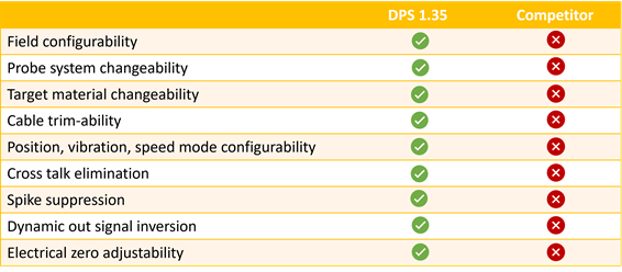
Both transducer systems use Triaxial Cables and easy probe/cable connecting mechanisms (VibeLock for Metrix, and Click Lock for Bently). The main differentiator comes with the DPS MX2033 driver or MX2034 transmitter. The MX2033/MX2034 has the following advantages over an Analog System:
- The MX2033 / MX2034 has superior amplitude and frequency resolution (see discussion above).
- The MX2033 can work with a 9m or 5m system without changing the Driver (less spare parts), other manufacturers need two drivers, one for a 9m system and one for a 5m system. Most drivers are limited to a single configuration (target material, probe and cable length).
- The MX2033 is interchangeable with the BN 3300XL, 7200 and 3300 Systems for both 9m and 5m systems (Most manufacturers would need six drivers to do the same thing).
DPS has many advantages over its competitor's product as shown in the chart below.

-
How compatible is the Metrix DPS with Bently Probes and Cables?How does the Metrix DPS perform with Bently Probes and Cables (3300XL, 3300, 7200)?
The Metrix MX2033 driver or MX2034 transmitter demonstrates outstanding linearity and meets API 670 specifications with other manufacturer's probes and extension cables.Each manufacturer of proximity probes and extension cables will have slight variation in their electrical properties during manufacturing, and therefore will have variation in their output. That is why API 670 specifies a linear range and variation to incremental scale factor. This gives manufacturers the necessary space to allow for variation in their manufacturing process.
If you run a curve for a Metrix MX8030 probe and MX8031 cable, or our Metrix MX2030 probe and MX2031 cable, with our MX2033 driver or MX2034 transmitter you will get a linear plot and the incremental scale factor will be within API 670 specifications. Likewise, by configuring the DPS to a Bently 3300XL probe and cable you will get very good results that are also within API 670 specifications, see below (Run 1 is Metrix MX8030, Run 2 is Bently 3300XL):
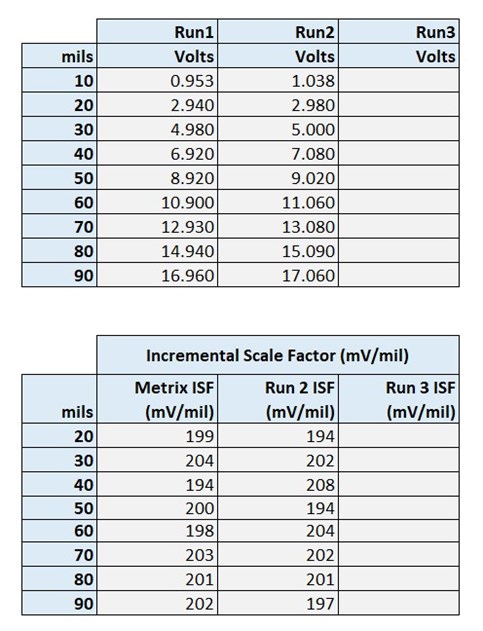
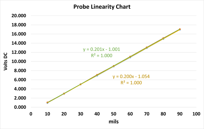
If the results for other manufactures, including Bently (even though there is a pre-programmed configuration for BN3300XL in the DPS menu), are not within API 670 limits for linearity and Incremental Scale Factor one can use a "Custom Configuration" to get within the limits.
-
How flexible is the Metrix Digital Proximity System compared to an Analog System?
The MX2033 driver can be used and configured for a variety of applications including different target materials and cable lengths. Other drivers are limited to the application, including target material and cable length.
Target materials can vary widely. The most common is 4140 Carbon Steel. This target material dominates the market. We have 33 different target materials listed on our website when ordering the MX2033 driver or the MX2034 transmitter, and there are others upon request. The biggest component that changes when choosing a different target material is the capacitor settings within the MX2033 driver. Other analog drivers have fixed capacitor settings based on what is ordered. The MX2033 driver can have its electrical settings adjusted by software.
A good example of this is when using our DPS Demo Kit to show the linearity of the 4140 Target Material, as compared to the Aluminum 6061 T6 material. During the Demonstration you are asked to run a probe curve using the 4140 target (demonstrating linearity), and then without changing the configuration run another probe curve using the Aluminum T6 target material (demonstration non-linearity). You are then asked to change the configuration to "Custom" that has the Aluminum configuration (correct capacitor settings) and run the probe curve again demonstrating linearity. This is an excellent demonstration to show how the DPS can adapt to different target materials.
See question 15 for the capability and flexibility of Metrix DPS systems.
-
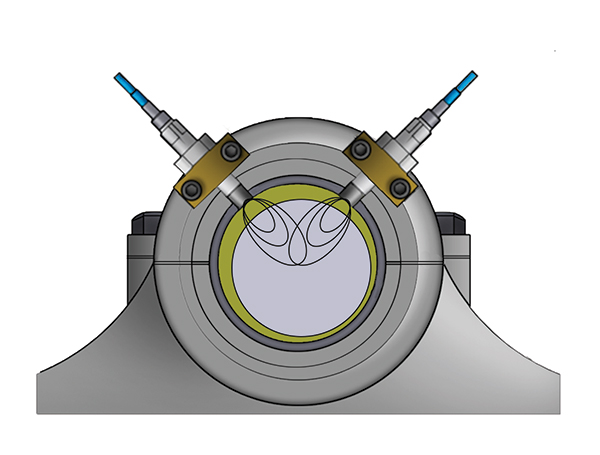
How does the Metrix TIGHTVIEW® application work versus a Narrow Side View product?

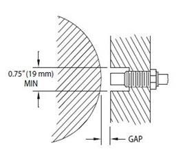
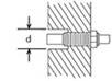
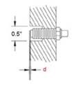
Metrix produces a proximity probe system that can fit in very tight spaces and provide an excellent linear measurement compared to a well-known competitor's narrow side view product. Typical clearances for our standard proximity probes are as shown:
Normal proximity probes usually need at least their probe tip diameter as clearance around the probe tip to ensure an accurate measurement. The above counter bore dimensions, 0.75" (19mm), are typical for a proximity probe to ensure there is no side interference at the probe tip. With the Metrix TIGHTVIEW® System, counter bores as small as 0.375" (9mm) can be used and still meet the API 670 linear range requirement. Also, with obstructions that are as tight as 0.05" (2.3mm) from one side of the probe, the API 670 linear range can also be achieved.

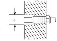

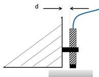
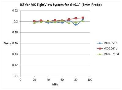
Using Metrix MX8030 5mm or 8mm Probe Counter Bore "d" to 0.375 inches (9mm) Using Metrix MX8030 5mm or 8mm Probe Obstructed Side View "d" to 0.05 inches (2.3mm) The following data set shows the Incremental Scale Factor (IFS) for the Metrix (MX) TIGHTVIEW® Probe System (5mm Proximity Probe) with various counter bore diameters ranging from no counter bore (open) to a counter bore of 0.375 inches (9mm) against a competitor's narrow side view product. The API 670 specification is a scale factor or 200 mV/mil + 5% for an 80 mil range (Note: 200 mV/mil = 0.2 V/mil). Notice that the Metrix TIGHTVIEW® Probe System performs very well and is in specification for the range.

 IFS for a Counter Bore "d" with Metrix (MX) TIGHTVIEW® System versus Competitor's Product (CP)
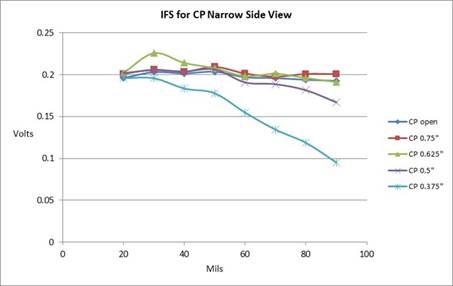

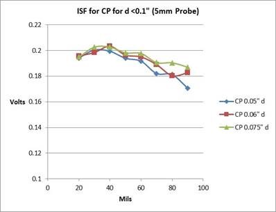
 The following data set shows the Incremental Scale Factor (IFS) for the Metrix (MX) TIGHTVIEW® Probe System (5mm Proximity Probe) with various obstructed side views from only one side ranging from 0.075 inches (1.9mm) to 0.05 inches (1.3mm) against a competitor's narrow side view product (see 3300 XL NSv Datasheet page 19 of 28). The API 670 specification is a scale factor or 200 mV/mil + 5% for an 80 mil range (Note: 200 mV/mil = 0.2 V/mil). Notice that the Metrix TightView Probe System performs very well and is in specification for the range.
 IFS for Obstructed Side View "d" Metrix (MX) TIGHTVIEW® System versus Competitor's Product (CP)


 Installation Variance - Another interesting feature of the Metrix TIGHTVIEW® Proximity Probe System is how the Metrix system holds up with regard to installation variance. This occurs when the 5mm probe is not completely flush with the counter bore or the side obstruction, like in the view below.The following data shows how the Metrix TIGHTVIEW® System behaves against a competitor's narrow side view system with a counter bore of 0.5 inches (12 mm) and an installation variance of + 10 mils (250 μm).
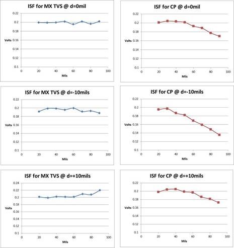
 This shows that the Metrix TIGHTVIEW® Proximity Probe System outperforms the competition and meets API 670 specifications. The TIGHTVIEW® System is available with the MX8030 5mm or 8mm Proximity Probe, associated Extension Cable, and with the MX2033 Driver and MX2034 Transmitter. See the Digital Proximity System webpage for the datasheet, or the product pages for the MX2033 Driver or the MX2034 Transmitter, and use option BB (09) to order.
 -
Do we need to select the TIGHTVIEW® option to reach BN NSv performance?
No. Our standard 8mm MX2030 or MX8030 probe, with a 5-meter, 7-meter or 9-meter system length, can meet BN NSv performance in a Tight Situation. Metrix has a very tight beam emanating from the probe tip. To reach API 670 performance in a Tight Situation, one would have to select MX8030 or MX2030 TIGHTVIEW®.
-
What is the advantage of the Metrix MX Series over the BN NSv proximity system in Tight Situations?
A “Tight Situation” is anytime there is not at least one probe tip diameter of clearance between the sides of the probe tip and a metal surface. Metrix designed the MX2030 and MX8030 probe series to be compatible with BN 3300 and 3300 XL. We have specifically designed improvements to our proximity probe systems (using the MX2033 Driver, or MX2034 Transmitter) that would outperform anything on the market, especially with regard to IGC Compressors (e.g. meeting API 670 requirements in a Tight Situation, cross talk elimination, extremely low amplitude resolution (0.1 mils pk-pk), no oil wicking or water ingression with our probe design, real thrust measurement – not virtual (20 mils is 20 mils, 500 microns is 500 microns, etc.), also, with our MX2034 Transmitter, in certain situations, one can use spike suppression to eliminate unwanted random spikes from the plant electrical system, and the ability to accurately measure speed up to 100,000 rpm).
-
Is the Metrix MX Series compatible with the BN NSv proximity system?
Yes and No, let us explain: Metrix prides itself with our ability to be compatible with BN. In the NSv case, if you just have to replace the BN NSv Proximitor, we can replace it with a MX2033 Driver configured for the BN NSv system, or you can use MX2034 transmitter in place of the BN NSv 990/991 transmitters, and it will work with the NSv Proximity Probe and Extension Cable and will meet specifications. If you have to replace the BN NSv probe or NSv cable you will have to replace the entire system with the Metrix System.
Benefits of the Metrix Digital Proximity System (DPS):
- Improved frequency and amplitude resolution.
- Reduced spare parts inventories.
- Flexible - the system can be used with other manufacturers proximity probes and cables.
- Regardless of manufacturer, if the probe curves are outside API 670 specifications for linearity and Incremental Scale Factor the DPS can be reconfigured to meet specifications.
- It can work in tight applications where normal probe clearances are not available.
- The same MX2033 driver or MX2034 transmitter can be used to look at different probe target materials (such as 4140 Carbon Steel, Stainless Steel, Inconel, 7075 T6 Aluminum, and others).
- The same MX2033 driver or MX2034 transmitter can provide API 670 specification probe linearity for 5m, 7m, 9m and other cable lengths (including legacy systems like the 7200, 3300, etc.).
- Easy to order probe mounting accessories.
- Short lead times (expedited deliveries available).