
Integrally Geared Centrifugal Compressor Monitoring
Overview
This whitepaper examines the basis for, and Metrix products designed to provide, continuous monitoring and protection of integrally geared centrifugal compressors – hereafter referred to as IGC Compressors. IGC Compressors fall into two broad categories, covered by two different well-known industry purchasing standards. American Petroleum Institute (API) Standard 617 covers “process compressors” suitable for handling not just air, but a wide range of process gases. API 617 is also broader in scope, addressing not just IGC designs, but axial compressors, single-shaft centrifugal compressors, and expander-compressors.
In contrast, API 672 defines a special class of IGC Compressors used only to compress air. These machines are generally smaller and feature a skid-mounted, packaged design that integrates the IGC Compressor along with its drive, controls, and all other auxiliaries. Hence, the title of API 672 describes the machines as “Packaged, Integrally Geared Centrifugal Air Compressors.”
Figure 1 provides a comparison of the key differences between IGC Compressors conforming to API 617 and those conforming to API 672. Figure 2 shows examples of each type of machine and the large difference in size that sometimes occurs for IGC Compressors in process service rather than plant air service.

Figure 1 – Comparison of key differences between process and packaged air IGC Compressors.

Figure 2 – The Ingersoll Rand CENTAC® (Centrifugal Air Compressor) shown on the left is a typical API 672 machine with a design that is a self-contained package consisting of the IGC, an induction motor drive, intercoolers, a control system, and all other auxiliaries. In contrast, the Atlas-Copco machine at right is a typical example of an IGC conforming to API 617. 617 machines are usually larger than packaged machines conforming to API 672, and unlike 672 machines, handle a wide range of gases – not just air.
- Unique Attributes of IGC Compressors
- Packaged Air Machines
- Process Machines
- Advantages and Disadvantages of IGC Compressors
- IGC Bearing Types
- Vibration Instrumentation
- Vibration, Thrust, and Speed Transmitters
- Machinery Diagnostics
- “Full Featured” Transmitters
- TIGHTVIEW® Applications
- Cross Talk
- 5mm Versus 8mm Probes
- Spike Suppression
- Temperature Stability
- Recommended Sensor Suite – API 672 Machines
- Recommended Monitoring System – API 672 Machines
- The 5580 / SW5580 on API 672 Machines
- Recommended Sensor Suite – API 617 Machines
- Recommended Monitoring System – API 617 Machines
- Typical System Arrangement
- Power Supply Considerations
- Enclosure Considerations
Unique Attributes of IGC Compressors
As the name implies, these are integrally geared machines, consisting of a large driving gear (main gear or “bull gear”) and numerous driven gears (pinions) on the shafts where the compressor impellers are located (Figure 3). Each pinion can thus run at a different speed, optimized for each impeller wheel. IGC Compressors are almost always multi-stage and thus have multiple impellers to raise the gas from the inlet pressure to the final discharge pressure via multiple compression stages.
Sometimes you will hear these machines referred to as “two-posters”, “three-posters”, “four-posters”, etc. and this is simply a reference to the number of impellers or stages. The machine of Figure 3, for example, is a “six-poster”. The machine of Figure 4, in contrast, is a four-poster. Process IGC Compressors can have has many as ten stages, while packaged air machines generally have only three or four. Indeed, innovations and efficiency improvements of the 1980s allowed air machines to utilize 3-stage designs instead of 4-stage while achieving the same flow and discharge pressures. This reduced the number of moving parts, energy consumption, and corresponding cost of ownership while improving reliability.

Figure 3 – Cutaway of a six-stage IGC showing main gear (M), three pinions (P1, P2, P3), and six impeller wheels (I1 – I6). The driving machine (prime mover) and coupling are not shown.

Figure 4 – Cutaway of a four-stage IGC showing main gear (M), four impeller wheels (I1 – I4) corresponding to each of the four stages, and six radial bearings (B1 – B6). The four yellow arrows show where the rider rings on each pinion shaft contact the rider rings on the bull gear and transfer them to the bull gear’s thrust bearings (B5 and B6 provide both axial and radial bearing surfaces for the main gear rotor). The red arrows show typical mounting locations / axes for optional accelerometers.
Another attribute of these machines is the extremely high shaft rotational speeds. While the bull gear almost always runs at speeds below 3600 rpm (North America 60 Hz electrical grid) and 3000 rpm (rest-of-world 50 Hz electrical grid), this is not true of the pinions. Except on extremely large process IGC Compressors with very large impeller diameters, the pinions run at speeds exceeding 20,000 rpm and as the impeller diameters decrease, the pinion speeds increase proportionately. Speeds as high as 60,000 rpm for the final compression stage are typical but can even exceed 70,000 rpm on very small machines.
The high speeds of the impellers mean that failure progression on these machines often occurs very quickly. For example, a shaft turning at 60,000 rpm equates to one revolution per millisecond. At these speeds, it is imperative to quickly detect excessive vibration and trip the machine. The high speeds, multiple pinons, gears, and overhung impellers also translate to complex rotor dynamics, both lateral and torsional. As a result, these were some of the earliest machines to be identified as candidates for continuous, proximity probe-based monitoring and protection systems.
Packaged Air Machines
Many industrial processes require compressed air – well beyond the petroleum, chemical, and gas sectors with which API is concerned. Consequently, in addition to the oil & gas sector, packaged air machines can be found in the general manufacturing sector including food & beverage, automotive, pharmaceutical, pulp & paper, cement, steel, glassmaking, and many others. However, regardless of the manufacturing sector in which found, the machines rarely differ and thus broadly conform to the requirements of API 672.
The quality of the ensuing compressed air from these machines is usually specified by referring to ISO standard 8573 which defines the purity of the air in three categories: particles, water (liquid and vapor), and oil. Classes 0 (most pure) to 9 (least pure) are used in each category. Thus, air with an ISO 8573 rating of 1:2:0 would have Class 1 purity for particulate contaminants, Class 2 purity for water, and Class 0 purity for oil. IGC Compressors are a particularly good choice when oil-free (Class 0) air is required, such as in the medical, pharmaceutical, electronics, and food & beverage sectors. Indeed, plant air compressors using an IGC design are often referred to as “oil-free” compressors by their manufacturers.
Process Machines
As shown in Figure 2, IGC Compressors used for process gases are typically larger than their API 672 counterparts and do not necessarily use a packaged design. These machines conform to API 617 and the requirements thereof. In addition, they and are frequently mounted on a foundation rather than a skid.
Advantages and Disadvantages of IGC Compressors
Besides the ability to provide Class 0 (oil-free) air, additional advantages of IGC Compressors include their small footprint relative to other compressor types with the same capacity, the need for only a single coupling, and a smaller number of impellers to reach a given discharge pressure. Interstage cooling is also easily accomplished on IGC Compressors, unlike other rotating compressor designs. IGC Compressors also often feature fabrication times 10-15% faster than other designs and prices 15-30% less.
However, disadvantages exist as well1. Each impeller needs to be sealed; IGC Compressors also involve more complex dynamic behavior, introduce more vibration and dynamic factors, and usually have narrower operating margins. Compared to conventional single-shaft API 617 machines without gears, integrally geared models have a shorter history in process plants, introduce more risks, less reliability, and more maintenance.
Although about 5% of IGC Compressors employ steam turbine drives, 95% or more are powered by induction motors that, with slip, run slightly below 50 or 60 Hz line frequency. It should be noted that IGC Compressors are not a good fit for variable frequency drives (VFDs) due to the aforementioned complex dynamic behavior – particularly torsional issues. Thus, in spite of lower prices and shorter fabrication times, IGC Compressors are avoided by certain process companies. Lastly, an IGC is more sensitive to unbalance than other compressor types. As such, processes that introduce impeller fouling and corresponding imbalance may not be suitable for IGC Compressors.
IGC Bearing Types
Almost all IGC Compressors use fluid-film (i.e., hydrodynamic) bearings for both radial and axial (thrust) support. However, certain very small IGC Compressors may employ rolling element bearings for carrying radial and axial loads. This is rare, and even when rolling element bearings are employed, they are used only on the main gear shaft; the pinion shafts remain supported by fluid-film bearings due to the damping and lower stiffness of such bearings compared to rolling element designs.
- Thrust Bearings
While thrust bearings are frequently found on pinion shafts, there is also another popular axial load-bearing scheme used on IGC Compressors: thrust rider rings. In this arrangement, only the bull gear shaft has thrust bearings. The thrust from the pinion shafts is transmitted to the bull gear by means of thrust rider rings. Figure 4 shows these rings and how those on the pinion shafts contact those on the bull gear. When there are two impellers on each pinion rotor, as in Figures 3 and 4, thrust is partially balanced by the opposing forces on each of the impellers and the thrust bearings consequently carry less load. Combination bearing designs that have both radial and axial faces are common in these machines; examples of such bearings can be seen on each side of the bull gear in Figure 4. - Radial Bearings
The impellers on an IGC are always overhung rather than suspended between radial bearings. The bull gear, in contrast, is suspended between bearings. The machine of Figure 3, for example, has eight (8) radial bearings: one for each impeller and two on the bull gear shaft. The machine of Figure 4 has six (6) radial bearings.
Vibration Instrumentation
As mentioned previously, the extremely high pinion speeds of IGC Compressors result in a very low ability to tolerate problems; failures propagate quickly and are often catastrophic. When vibration monitoring based on proximity probes was becoming more popular in the 1960s due to their ability to directly observe the shaft and its motion, IGC Compressors were at the forefront of machines in need of such monitoring. In fact, Joy® Compressors was one of the earliest adopters of continuous machinery monitoring and was one of several pioneers in the area of integrally geared centrifugals. As Joy made proximity probes and continuous monitoring systems standard offerings on their machines, other manufacturers quickly followed suit, including Borsig, Worthington, Elliott (now FS-Elliott) with its PAP (Plant Air Package) models, and Clark with its ISOPAC® models. Ingersoll Rand followed in 1968 with introduction of its CENTAC® (Centrifugal Air Compressor) models. Today, there are many other excellent manufacturers of these machines; the foregoing list is not intended to be exhaustive. It simply recounts several of the earliest adopters of continuous monitoring systems based on proximity probes.
Extending as far back as the 1960s, IGC manufacturers were very cost-conscious. The original monitoring systems supplied with these machines thus departed from so-called API 670 monitoring systems which were more full featured. For example, where API 670 demanded individual readouts for each channel, the systems used to monitor API 672 machines typically shared a single readout that was switched between channels. In time, manufacturers of API 672 machines departed from stand-alone vibration monitors entirely and began to use vibration transmitters instead, preferring to use the IGC’s own control system to provide monitoring and alarming functionality. Consequently, API 672 machines do not default to API 670 instrumentation. While the user may request it as an option when ordering a machine, the default offering is instead a far more basic system based on transmitters along with fewer measurement points than are typical of other classes of turbomachinery such as API 612 steam turbines, API 616 gas turbines, API 617 compressors, and API 613 gears. This basic level of instrumentation has proven adequate for API 672 machines and allows OEMs to offer the machines at more economical prices than their process compressor counterparts conforming to API 617. Table 1 summarizes the key differences between the suite of transducers and monitoring system approaches used by default for API 672 packaged air compressors and those used by API 617 process compressors.
Vibration, Thrust, and Speed Transmitters
A vibration transmitter takes the overall amplitude of the signal and converts it to a proportional 4-20mA signal where 4mA is bottom of scale (usually zero) and 20mA is full scale. Figure 6 illustrates the concept for a radial vibration probe observing a shaft that is vibrating at 0.7 mils pk-pk and connected to a transmitter with a full-scale range of 2.0 mils. Other transmitter types (such as those used for axial position probes) can be used to ignore the AC component of the signal and look only at the average gap (rather than instantaneous gap). Still other transmitter types can be used to count pulses as gear teeth (or a shaft discontinuity such as a keyway), pass across the probe’s field of view. The rate of such pulses corresponds to the shaft’s rotational speed.
Many transmitters are loop-powered, meaning the PLC, DCS, or other control system provides industry-standard +24Vdc excitation for the connected transmitter, eliminating the need for a separate power supply and corresponding wiring.
 Figure 5 – Orthogonal (X-Y) radial proximity probes are separated by 90° and thus observe shaft motion in both X- and Y-planes.

Figure 6 – A vibration transmitter converts a single aspect of the raw signal into a proportional 4-20mA signal. For a radial vibration transmitter, a peak detector converts the AC amplitude of the dynamic (raw) signal into a proportional DC current compatible with PLCs, DCSs, and other systems – such as those used to control an IGC.
If detailed vibration analysis is required using the dynamic (raw) signal, the vibration specialist can go to the BNC on the Metrix MX2034 Proximity Transmitter, usually mounted in a junction box on the machine skid. The MX2034 conforms to the industry-standard convention (Figure 7) of decreasing gap (motion toward the probe) resulting in a positive-going signal.

Figure 7 – The industry-standard convention for the output from a proximity probe system is specified in API 670. The Metrix MX2034 Proximity Transmitter can take either a +24Vdc excitation or -24Vdc excitation and provide the industry standard output at the BNC of decreasing gap is a positive going signal.
The Metrix MX2034 Proximity Transmitter can take either a +24Vdc excitation or -24Vdc excitation and provide the industry standard output at the BNC of decreasing gap is a positive going signal. The Metrix MX2034 provides a software-configurable capability to internally invert its buffered output signal depending upon user preference (see Figure 8).
The MX2034 Proximity Transmitter can have a loop up to 5000 meters (2 miles) and maintain accuracy. It is important when using test equipment that you do not create a ground loop. While this is usually not a problem with battery-powered or isolated test equipment where a “floating” ground is present, it can create issues when AC-powered test equipment does not have adequate input impedance (50K ohms minimum) and the system is plugged into an outlet with a ground lug. Metrix transmitters are designed to tolerate connection to external devices as long as they do not introduce a voltage. Ground loops can be one source of differing potential. Another can be the sensor power setting6 found on some portable data collectors. Either one can introduce an external voltage to the transmitter that can affect the integrity of the 4-20mA signal and corresponding monitoring integrity.
Machinery Diagnostics
A transmitter-based system is readily understood by instrument personnel, can provide reliable machinery protection, allows trending of the transmitter’s output, allows local display of values and alarm statuses at the IGC’s control panel, and eliminates the need for (and cost of) a stand-alone monitoring system.
In the rare case, when the 4-20 mA signal indicates early warning of a machine issue, a technician or engineer can connect to the BNC connector with a coaxial cable between the transmitter and the diagnostic instrument, such as a portable vibration analyzer, oscilloscope, or other data acquisition / analysis instrument. As noted earlier, Metrix provides an industry standard output of reduced gap providing a positive going signal, other manufacturers of proximity transmitters may not. This makes it convenient to diagnose and machinery issue.
The Metrix MX2034 digital proximity system transmitter dynamic signal output from the 4-pin terminal block is short-circuit protected and can drive longer cable lengths (up to 100 meters or 375 feet) than the BNC connector which is limited to 5-meters (16 feet).

Figure 8 – The usual convention is for negative polarity at the BNC, as described in API 670. The configuration software for the MX2034 Digital Proximity System allows the user to invert the polarity of the raw signal at the BNC connector and at the wiring terminals (SIG, COM) shown in Figure 9.
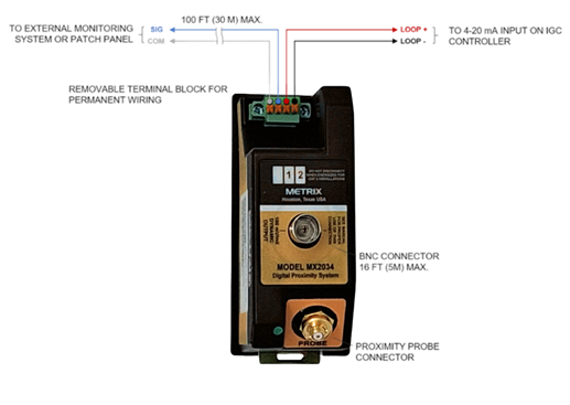
Figure 9 – The 4-20 mA loop can extend up to 5000 meters (2 miles). In addition to a BNC connector for temporary connection to test instruments (5 meters (16 ft)), the MX2034 Transmitter has provisions for permanent wiring to patch panels or external monitoring system (such as for continuous condition monitoring) by means of terminal block connections. The permanent wiring output can drive cable lengths up to 100 m (325 ft) and, like the BNC connector, is short-circuit protected and provides an industry standard output.
It is important to note, Metrix recommends that the complement of transducers required for 617 compressors (summarized in Table 1) be installed on 672 compressors, even if the additional probes and accelerometers are not permanently monitored – at least they will be installed in the machine already and available if needed.

For existing machines, this should be planned during a scheduled maintenance outage and included in the scope of work. For new machines, suppliers of API 672 machines will almost always have a standard option for inclusion of these additional sensors.
For example, API 672 machines do not come by default with phase trigger probes installed on the pinions. Without these sensors, the ability to do proper machinery diagnostics is greatly hampered and the probes are rarely externally accessible. Nor are the pinion shafts typically exposed, allowing installation of a temporary phase trigger using an optical sensor and reflective tape on the shaft. Retrofitting phase trigger probes on pinion shafts means pulling covers. A better practice is to specify installation of these probes at time of manufacture, or to retrofit them during a planned outage so they are available when needed. Because they are a standard option within the API 672 purchasing specification, it is simple to include them at time of purchase.
The bull gear does not typically come with axial or radial vibration probes as this part of the machine turns at appreciably slower speeds and is usually not as prone to problems as are the pinion shafts which turn at much higher speeds. However, it is still a good idea to ask the OEM to install these probes for the reasons noted above.
When diagnosing gear problems, the situation is easier because the accelerometers are mounted externally, and on IGC Compressors conforming to API 672, the OEM is required to make provision for two accelerometers by drilling and spot-facing suitable mounting areas – usually on the bull gear bearing housings in both horizontal and vertical axes. However, mounting locations at the pinion bearings can also be suitable – if accessible. The diagnostic engineer has merely to provide suitable accelerometers and mount them in these existing holes. The bull gear is usually designed with a service life of 25 years or more, but if gear issues arise frequently, these accelerometers can be left permanently in the machine and monitored via an appropriate device such as the Metrix 5580, discussed in more detail later in this application note.
“Full Featured” Transmitters
Metrix has historically filled an important niche in the machinery condition monitoring and protection market by offering cost-effective solutions suitable for critical machinery. Less critical machines do not require stringent adherence to industry standards such as API 670, suitable for the most critical turbomachinery. They instead require systems with a feature set and corresponding price commensurate with the economics of the machine, the service it provides, its failure mechanisms, and the consequences of failure. The standard instrumentation package on API 672 machines is a prime example – adequate, and reliable but less expensive than a 670 system.
The primary way in which Metrix addressed this niche for more economical monitoring solutions was by pioneering the concept of vibration transmitters. The original model was designed to measure seismic vibration and evolved into what is today’s ST5484E (where ST standard for “Seismic Transmitter). Later, Metrix began to introduce models that could accept proximity probes. Original models used analog circuit designs. In 2003, digital designs were introduced with the Metrix TXR (Transmitter Radial) and TXA (Transmitter Axial). Still later, in 2012, Metrix introduced the Digital Proximity System (DPS) with model MX2033 for a conventional API 670 driver and model MX2034 for a software-configurable transmitter that could be applied for radial vibration, axial position, or speed measurements using software available to the user. The software-configurable features of the DPS have continued to improve over the last decade and one of the most important new features is one that allows mounting of probes in tight spaces, as discussed next.
TIGHTVIEW® Applications
The relatively small shaft diameters, encountered in IGC Compressors, particularly those in the latter stages of the compressor where smaller pinions and impellers are used, means that it can be difficult to maintain the tip separation, counterbores, and/or adjacent surface separation required by conventional proximity probe systems. This is especially true in packaged air compressors, as most are substantially smaller than their process compressor counterparts.
The clearance requirements for a conventional Metrix proximity probe system (and those of most other manufacturers) are shown in Figure 10. In many cases, these are too large to address API 672 machines. To address the needs of the smaller geometries incurred by many 672 machines, some manufacturers have introduced different probes, cables, and drivers or transmitters that permit reduced clearances and tip spacing. However, these measurement chains use completely different components (probes, cables, drivers/transmitters) than applications where standard clearances can be observed. As such, spare parts burdens increase as most users have a mix of machines in their plants that require both standard and so-called “narrow field” proximity probes.
 Figure 10 – Proximity probes require sufficient spacing with respect to sidewall clearance, counterbore clearance, and tip spacing. The target diameter must also be sufficiently large so that discontinuities (such as the periphery of a shaft) are outside the probe’s field of view. This can be challenging on IGC Compressors due to the small shaft diameters and confined geometries encountered. Dimensions shown here are for standard Metrix proximity probe systems. Other manufacturers may have even larger clearance requirements.
To allow users to incorporate standard measurement chain components, Metrix has introduced a feature called TIGHTVIEW® that compensates the gap-versus-voltage curve (see Figure 7) when an application cannot maintain standard clearances. This compensation allows use of standard 5mm and 8mm probes and cables while delivering a linear curve, even in mounting geometries that reflect insufficient clearances.
To apply TIGHTVIEW® capabilities to a given measurement chain, the user simply employs the system’s configuration software to indicate that the probe will incur reduced clearances. Special compensation is applied to accommodate these constraints while keeping the probe’s response curve linear and to maintain its full 80 mil (2 mm) linear range. This innovation permits customers to use the same probes, cables, and drivers or transmitters throughout their plants, whether conventional or reduced-clearance applications are encountered. This means that TIGHTVIEW® capabilities are merely a configuration setting – not entirely different proximity measurement chain components.
An informative video showing the system in operation and demonstrating its performance is available on the Metrix website. Factory TIGHTVIEW® ordering options allow the minimum counterbore clearance of Figure 10 to be reduced to 0.5” (12mm) using 8mm probes and 0.313” (8mm) using 5mm probes. Furthermore, sidewall clearance and minimum target size can likewise be reduced significantly through TIGHTVIEW® Custom Calibration using the DPS Software. The ability to reduce the tip spacing, however, relies on a different configuration setting, discussed next.
Cross Talk
When required tip spacing is not maintained, the fields from adjacent probes interfere with one another. This is depicted in Figure 11.

Figure 11 – Crosstalk occurs when the fields from adjacent probes interfere with one another. The probes on the left maintain sufficient spacing and their fields thus do not interfere with each other. In contrast, the probes on the right are observing a small-diameter shaft and their fields interfere with one another.
To generate the electromagnetic field that emanates from a proximity probe, a coil inside the probe is excited at a particular oscillation frequency. When two probes are situated with insufficient spacing between them, the probe fields interact with one another and the small difference in excitation frequencies between the two oscillators results in a beat frequency (Figure 12). This beat frequency manifests as so-called “cross talk” which affects the accuracy of the probe readings, and this is why minimum tip spacing requirements exist.
 Figure 12 – In conventional applications, the oscillator-demodulators for all probes run at essentially the same frequency and even though these frequencies differ slightly, they do not interact with one another. However, in confined spaces, minimum probe tip separation cannot be maintained and the interaction of the two, slightly different oscillator frequencies results in a beat frequency that is erroneously interpreted as a changing gap (i.e., vibration) – commonly referred to as cross talk.
However, the Metrix DPS has a software-configurable option that eliminates this cross talk and allows probes to be spaced much closer together without interfering with one another. It works by assigning suitably different frequencies to each adjacent probe, eliminating a beat frequency within the range of the probe’s normal frequency response. This setting can be seen in the upper-left corner of the configuration software shown in Figure 8. A drop-down box allows the user to assign either the X frequency (default) or the Y frequency to any given probe. The result of these different frequencies is shown in Figure 13. The setting is available in both the transmitter version and driver version of the oscillator-demodulator. It can be applied to any two adjacent probes – whether a radial X-Y pair, dual-voting thrust pair, or other – such that they no longer interfere with one another.

Figure 13 – By default, all probes within a given family are shipped with the same oscillator frequency (top). Because of small variations in the oscillator circuits, two probes will oscillate at nearly (but not identically) the same frequency and when physically spaced too closely will result in the beat frequency depicted in Figure 12. However, by assigning suitably different frequencies to each probe (bottom), cross talk is eliminated. The Metrix DPS provides this capability as a software-configurable Cross Talk Elimination feature.
5mm Versus 8mm Probes
5mm and 8mm probes use identical coils and are thus electrically identical. However, the physical size of the probes is different, as shown in Figure 14. Because the tip encapsulation in an 8mm probe is thicker, the probe body is larger and comes in thread sizes of 3/8-24 UNF-2A (Imperial) and M10x1 (Metric). The larger probe body and the additional encapsulation results in a physically more robust probe, and 8mm probes are thus recommended for all applications where sufficient mounting space allows.

Figure 14 – 5mm (top) and 8mm (bottom) proximity probes differ in their physical – not electrical – characteristics because they use identical probe coils but different physical packaging. The probes are drawn to scale. The 8mm probe features more PPS encapsulation around the probe coil and a larger case size supporting larger threads. The 5mm probe features less encapsulation around the probe coil and a smaller case size supporting smaller threads. IGC Compressors often use the smaller physical size of 5mm probes due to the small machine geometries and corresponding lack of space for mounting larger 8mm probes.
As mentioned, 5mm probes use the same coil as 8mm probes and are thus electrically identical, featuring the same linear range (80 mils or 2mm) as 8mm probes. However, because the probe tip diameter is smaller (5mm), there is less encapsulation surrounding the coil. The probe case is likewise smaller in diameter and comes in ¼-28 UNF-2A (English) and M8x1 (Metric) thread sizes. Because the case of a 5mm probe has a thinner wall thickness, it can sustain only one-fourth as much torque as an 8mm probe case before breaking. This is not to say that 5mm probes are extremely fragile – simply that they are less robust than 8mm probes and are consequently recommended only when the larger physical size of an 8mm probe is incompatible with the machine’s geometries.
Spike Suppression
Most monitoring system algorithms that accept the signal from a driver will ignore non-periodic spikes, preventing them from affecting the peak detector. In transmitters, special provisions have been made to suppress non-periodic spikes in the vibration signal. Although infrequent, non-periodic spikes can arise from numerous sources including lightning, breakers opening/closing, power supply surges, handheld radios being keyed, and other transient electrical phenomenon.
It is important to note that these spikes are not due to mechanical glitch on the shaft (such as a scratch or improper surface finish), residual magnetism in the shaft, or other factors that result in electromechanical runout. The proper way to deal with runout is to remove it – not to mask it. However, spurious electrical noise is by its nature aperiodic and transient. It is not the same as runout and different methods exist for mitigating it.
In the MX2034, spike suppression is a software-configurable option that can be enabled or disabled by merely checking a box. The feature works by detecting short-duration (i.e., less than 25 milliseconds) spikes in the waveform that have an amplitude above a threshold level. It looks to see whether these are repetitive (in which case they are not ignored) or aperiodic (in which case they are ignored). Refer to Figure 15.
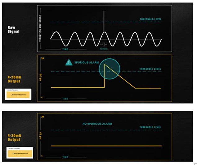
Figure 15 – Example of how Spike Suppression prevents an electrical spike from impacting the 4-20 mA signal.
Spike suppression is not new and has been offered on proximity transmitters from other suppliers as a factory-special hardware modification. However, because the MX2034 is a digital device, and fully software configurable, such features do not require special hardware and allow a single device to be used for all applications.
Temperature Stability
The physics of compression, whether air or some other compressible fluid, demand that the gas becomes hotter as its density increases. As a result, the latter stages of IGC Compressors can become quite hot, even when intercooling is used between stages, as is common on all IGC Compressors. This translates to probe environments in which elevated temperatures are regularly incurred. Early proximity probe systems dating back to the 1960s and 1970s suffered from poor linearity with temperature changes. Many advances have been made in the intervening decades to deliver proximity systems with a wider range of operating temperatures over which linear performance is assured. Indeed, some of the major advances to probes over the years are in the realm of temperature stability and physical robustness. Metrix probes and extension cables are designed for operating temperatures of up to 177°C (350 °F). The transmitters/drivers, on the other hand, are mounted off of the machine in junction boxes and thus usually do not encounter the same elevated temperatures as probes and extension cables. They are designed for operating temperatures up to 85°C (185 °F).
Recommended Sensor Suite – API 672 Machines
API 672 requires IGC Compressors built to comply with the specification be fitted with a transmitter-based monitoring system for X-Y radial vibration at each impeller. Although axial position measurements for thrust bearings are not mandated, and thrust bearing temperatures are used instead, many customers prefer to include axial probes nonetheless and Metrix recommends this as a best engineering practice. For machines with thrust rider ring designs (see Figure 4), the thrust probes are located on the bull gear shaft as this where the thrust bearing(s) is (are) situated. For machines without rider ring designs, the thrust bearings will instead be located on the impeller shafts. To reduce losses and maximize efficiency, the clearance between impellers and volutes are kept as small as possible, tolerating very little axial movement before a rotor-to-stator rub is incurred. Given the extremely high speeds of the impellers (tens of thousands of rpms), catastrophic damage can occur in fractions of a second.
For diagnostic purposes, a phase trigger probe installed on each impeller shaft can be invaluable. Although such probes are not used as part of the machinery protection scheme, and are optional, Metrix recommends that they be specified at time of purchase and installed. For such probes, the corresponding transmitter is generally set to condition the signal into a speed measurement. Although the gear ratios of each pinion allow the speed of each stage to be calculated from the bull gear speed, the speed measurement as a direct input to the condition monitoring instrument will still be useful for the vibration analyst conducting machinery diagnostics. Of even greater importance, however, is the once-per-turn reference that a phase trigger probe provides. This allows the analyst to compute vibration phase for each radial probe on the pinion shaft (usually four probes) and opens up a much larger capability to perform diagnostics than when phase information is not available to the analyst.
For all of these reasons, Metrix recommends that API 672 machines be fitted with the same complement of proximity probes as API 617 machines. This information is summarized in Table 1.
Metrix 8030 8mm probes or 2030 5mm probes and companion extension cables are used to make these measurements.
It is rare for casing acceleration measurements to be permanently monitored. It is more common for accelerometers to be temporarily installed to assess gear condition. API 672 machines are automatically shipped with mounting provisions for such transducers, but not the transducers themselves. In the event a customer wants to monitor such sensors permanently, a suitable transmitter can be used, such as the Metrix 5580 software-configurable signal conditioner, which filters the acceleration signals to the range of interest and provides a proportional 4-20mA output to the IGC Compressor control system. Of substantial importance to the analyst will be easy access to the raw, unfiltered accelerometer signal so that gear-related problems can be identified using the full frequency range of the sensor. With pinions that turn at tens of thousands of rpms, the gear mesh and tooth passing frequencies will be even higher and only an accelerometer (not a piezo-velocity sensor) will be capable of encompassing this range. The red arrows in Figure 4 show typical mounting locations for these accelerometers, but this will vary by manufacturer and correspond to their recommendations for locations where transmission of gear-related frequencies is maximized. The Metrix SA6200A accelerometer is an excellent choice for gear measurements as well as many other applications. Summary specifications pertinent to gear measurements are below.

Recommended Monitoring System – API 672 Machines
The monitoring system specified under API 672 for packaged air compressors is composed of proximity transmitters into the machine’s control system where alarming, trending, and display is accomplished. The controller thus becomes the monitor. The signals come into the controller as proportional 4-20mA values. For radial vibration, the 4-20mA signal is proportional to the pk-pk vibration amplitude. For axial position, the 4-20mA signal is proportional to the average probe gap. For phase triggers, the probe observes a once-per-turn discontinuity (usually a notch such as a keyway or specially machined hole) and the transmitter converts this into a proportional 4-20mA value corresponding to shaft rotative speed. The real value in the phase trigger sensors is not so much one of speed indication as it is in the ability to use vibration phase when conducting diagnostics.
API 672 air machines have employed transmitter-based systems for more than 35 years and it is exceedingly rare to find an air machine in the field without proximity systems near each of the compressor impellers. In the event an unmonitored machine is encountered, or (more likely) the installed system is quite old and in need of replacement, the Metrix MX2034 proximity transmitter is recommended. A typical system arrangement diagram for an API 672 machine is depicted in Figure 16.
There are numerous features in the MX2034, most of which have already been discussed previously, that address the needs of API 672 machines. For convenience, these are summarized below.
- Universal Configurability
The MX2034 is software-configurable for measurement type, probe type, full-scale range, and all other settings. This allows a single device to be used for radial vibration, axial position, and speed (phase trigger) measurements without need of carrying different transmitters for different measurements. Older analog designs require different devices for not just different measurements, but different full-scale ranges. - TIGHTVIEW® Capabilities
The MX2034 does not require different probes and cable types from those typically used elsewhere in the plant. This is because standard probes and cables can be used and adjusted for restricted clearance applications by simply configuring the signal conditioner (transmitter) appropriately. Other systems require special probes, cables, and transmitters to be used that are specifically designed to limit the probe’s sideview by employing different coils in the probes to give a narrower field. This means that many plants must stock not only different transmitter types, but different probe and cable types compared to those used in their other machines. The Metrix DPS eliminates this requirement by allowing standard probes and cables to employ the special TIGHTVIEW® configuration in the transmitter. - Field Changeable Options
Necessary changes in the field can be accomplished by simply connecting the MX2034 to its configuration software and making the desired changes – not by purchasing a device with different “hard wired” configuration such as probe type, measurement type, and full-scale range. - Signal Polarity Inversion
The MX2034 comes standard with negative polarity at the buffered output or BNC, which is standard for a proximity sensor. It can also be configured in software to invert the signal polarity at its buffered outputs, something not possible with other loop-powered proximity transmitters which require the use of special external adapters. - Separate Permanent Wiring Terminals Supporting Longer Cable Runs
In addition to the BNC connector on the device, the MX2034 has permanent wiring terminals designed for connecting the raw signal to patch panels and permanent condition monitoring systems that are located some distance from the machine skid. Many other transmitters have only two wiring terminals: those for the 4-20mA output. The raw transducer signal is only available at a BNC connector, only suitable for temporary connections, and only suitable for cable lengths of 5m (16 ft) or less. The MX2034, in contrast, provides the raw signal at permanent wiring terminals and allows up to 100m (325 ft) of instrumentation cable, extending the raw signal to more convenient locations than simply a junction box at the machine skid. This allows the 4-20mA loop to be input to the IGC compressor control system where all protective functions and alarming are accomplished, and the raw signal to be connected to a separate environment where condition monitoring is done – either periodically by connecting a portable analyzer / data collector to a patch panel, or permanently by connecting to a stand-alone condition monitoring and data acquisition system. - Cross Talk Elimination
The small physical geometries and clearances in many IGC Compressors conforming to API 672 mean that probes must often be placed on small-diameter shafts where target size is limited (such as dual-voting axial measurements) or tip spacing cannot be maintained (both axial and radial measurements). This allows cross talk to occur. The MX2034 allows the user to set adjacent probes to two suitably separated frequencies, eliminating cross talk and allowing probes to have closer physical spacing than would otherwise be possible. - Same signal conditioning algorithm
Metrix transmitters set the original de facto industry standard for the peak detection algorithm used on air machines conforming to API 672. Users can confidently replace their aging analog transmitters with the Metrix DPS, knowing that readings meet API 670 accuracy requirements, historical trends can be compared to current trends, and alarm setpoints do not have to be re-established.
Compatibility with the IGC Control System
Virtually all IGC Compressor control systems are designed to accept the 4-20mA signal from radial vibration, axial position and speed transmitters. The MX2034 provides this in an industry-standard ISA SP50 format and is loop-powered by the +24Vdc excitation available from the IGC’s control system. The MX2034 will be a form, fit, and function replacement for most older installed transmitters, and can even be used to replace separate stand-alone monitoring systems found on old IGC Compressors dating back to the 1960s, 70s, and 80s.
The 5580 / SW5580 on API 672 Machines
The Metrix 5580 Smart Signal Conditioners is a two-channel unit. The SW5580 Smart Signal Conditioner and Switch comes with integral alarming and relay capabilities to provide a self-contained machinery protection system. The family was designed to cost-effectively address machinery that does not warrant the cost and complexity of a rack-based system. It is a right-sized solution for many machines and offers an appropriate feature set.
The basic 5580 is essentially an externally powered universal vibration transmitter that can accept input from most any vibration sensor, convert it to a proportional 4-20mA signal, display it in engineering units, and provide true isolation of the raw signal. This raw signal is available locally at a BNC connector on the device and also at wiring terminals suitable for connecting up to 300m (1,000ft) of wiring without use of a line amplifier. This allows more flexibility than with the 300m (1,000ft) limitation of most vibration sensors on the market.
As noted previously, the MX2034 will most often be the appropriate choice for API 672 machines. However, the 5580 can augment the MX2034 by allowing permanent monitoring of accelerometers on the gearbox. The 5580 provides a proportional 4-20mA output based on the acceleration signal amplitude. As such, it functions as an accelerometer signal conditioner and transmitter.
There may also be select instances where users require the integral display of the 5580, and the up to 300m (1,000ft) of wiring that it can drive with the raw dynamic signal when connecting to patch panels or separate Vibration Monitoring Systems (VMS) and or Condition Monitoring Systems (CMS). In these instances, the 5580 can be used to monitor API 672, as well as API 617, machines. It should be noted that the 5580 accepts proximity probe drivers. Even though the 5580 can accept any API 670 rated proximity system, the MX2033 Driver provides many of the same features of the MX2034 Proximity Transmitter relevant to users of IGC Compressors; namely, TIGHTVIEW® configuration, cross talk elimination, and preservation of API 670 signal polarity conventions.
Recommended Sensor Suite – API 617 Machines
Machines conforming to API 617 will generally ship with a larger complement of sensors than will API 672 machines. In the event the machine does not have the sensor suite described in Table 1, it is recommended that it be retrofit with the types, quantities, and locations described therein. Because the phase trigger can be such a valuable diagnostic enabler, it is further recommended that spare phase triggers be installed on each shaft, as per the standard option in API 670 §6.1.5.2 advocating this best practice.
Recommended Monitoring System – API 617 Machines
The default monitoring system for API 617 machines is one conforming to API 670. Indeed, a salient aspect of API 670 systems that distinguish them from the integrated system of API 672 machines (i.e., where the machine controller is the monitor) is that a 670-compliant system must be independent of the machine control system (see API 670 5th Edition, §4.8). This requirement of the 670 standard is to ensure that a failure of the control system itself will not defeat the machinery protection functionality.
The consequences of failure for a packaged air compressor are typically related to process downtime and mechanical repair costs. In fact, because of their packaged design, rapidly swapping out a failed machine for another one is feasible. In contrast, this is rarely (if ever) feasible for process compressors. In contrast, the consequences of failure on an API 617 process compressor can often encompass the process, the mechanical repair costs, and most importantly, release of hazardous substances and/or a fire/explosion hazard. The stakes are often thus higher, and hence the need for a segregated system providing machinery protective functions.
Similar capabilities, however, can be provided in a system that more closely resembles transmitters, but with additional features and user conveniences. The Metrix SW5580 strikes an excellent balance between affordability and functionality while providing a fully segregated machinery protection solution that is functionally and physically independent of the machine control system. For this reason, it is a good choice for many API 617 machines where it is undesirable to integrate its machinery protection within its control system by using a transmitter-based approach. The SW5580 has a number of right-sized features appropriate for API 617 IGC Compressors, as described next.
Integral Alarming / Relays
The SW5580 provides integral alarming capabilities and solid-state or electromechanical relays to externally annunciate and transmit these alarms for indication and machinery protection (i.e., auto-shutdown) purposes. The non-SW version is intended for installations where a PLC, DCS, or other control/automation platform is available for accepting the 4-20mA output of the 5580 and proving the alarming. The SW version is used when self-contained alarming and machinery protection capabilities are required.
Universally Configurable Design
Prior generations of signal conditioners and monitors consisted of different models for different measurements. One model was required for radial vibration measurements, another for axial position, another for acceleration measurements, another for velocity measurements, and another for speed. In contrast, the 5580 uses a fully software configurable design that allows it to be configured for any measurement. This reduces personnel training costs and spare parts burdens. It also ensures that changes to measurements can be done entirely via software, in the comfort and safety of an office environment, and then the device can be installed in the field.
Two-Channel Modularity
Prior Metrix signal conditioners and monitors were single-channel designs where two channels required twice as much space and twice as much hardware. The 5580 and SW5580 provide two independently configurable channels. For example, one channel can accept a proximity probe for axial position monitoring and the other channel can accept a seismic sensor for radial bearing vibration. The device can also be configured for “dual-path” monitoring whereby a single sensor is processed in two separate paths to provide two separate measurements. For example, a single accelerometer mounted on a bearing housing could monitor acceleration on Channel 1 to monitor bearing condition and integrated velocity on Channel 2 to monitor for rotor-related faults like unbalance and misalignment. The two channels can have their own alarm setpoints that are independent of the other channel.
The devices are also modular in that they can be supplied with only a single channel enabled and priced accordingly. The second channel can be enabled in the field, at a later date, using a special firmware key supplied by the factory, eliminating the need to swap out two-channel hardware for one-channel hardware.
Multi-State LEDs
Alarm and status conditions are clearly annunciated at the device via multi-state LEDs as follows:


There is one LED for each channel, allowing separate and unambiguous status annunciation for each measurement and sensor.
Universal Inputs
The 5580 and SW5580 support most commercially available acceleration, velocity, and proximity sensors, including the provision of any necessary sensor power. A single +24Vdc connection powers the device, its 4-20mA output(s), and its connected sensor(s) –including the -24Vdc power required by proximity transducers and the constant current required by IEPE accelerometers and piezo-velocity sensors. For API 617 machines, the proximity measurement chain will normally consist of the MX8030 8mm proximity probe, the MX8031 extension cable, and MX2033 driver. For machines with competitive API 670 compliant proximity probes already installed, the 5580 / SW5580 are fully compatible.
Integral 4-line, Dual-Channel OLED Display
The device’s backlit OLED display ensures that readings are available locally rather than only at the HMI for the PLC, DCS, or other controller. Both channels that are enabled, display continuously and simultaneously to include the channel number, the 4-20mA output value, the measured value, and the associated engineering units.
Individual, Configurable Relays
For the SW model, four (4) relays are provided, two for each channel. This allows ALERT and DANGER to be separately annunciated for each channel. The relays can be configured for latching or non-latching operation, normally energized or normally de-energized. Normally Open (N.O.) and Normally Closed (N.C.) wiring terminals are provided. Users can choose from either solid-state (SPST) or electromechanical (SPDT) relays at time of ordering. Solid-state relays are typically used for providing logic-level alarm status to controllers and other devices. Electromechanical relays are typically used to switch interposing relays, fuel valve solenoids, or other trip devices as part of the machine’s control where the signal being switched is larger than a logic-level voltage.
Local Buffered Outputs
Conventional BNC connectors for each channel are provided for easy connection to portable instruments such as data collectors, DVMs, and analyzers where the cable length does not exceed 16 feet (5 meters). These outputs are fully isolated from the 4-20mA outputs to ensure connection of external devices do not compromise the integrity of the monitoring or protective functions.
Amplified Buffered Outputs
When devices are mounted in junction boxes at the machine, it can be inconvenient to open the box to connect portable instruments. In prior generations of Metrix devices, and on most commercially available monitors, the buffered outputs are not suitable for wiring runs exceeding 5-10 meters without use of an external amplifier to drive the raw signals over long distances. The 5580 / SW5580 overcomes this limitation by employing integrated signal amplification, allowing buffered output signals to be driven up to 1000 feet (300 meters) without distortion. The amplified signal is available at wiring terminals and is intended for permanent connection to remote patch panels or other condition monitoring systems.
Another important aspect of these buffered outputs is that when an external condition monitoring system is connected, it is completely independent of the machinery protection system. Increasingly, customers are demanding that systems accessible over the internet (such as condition monitoring) be fully segregated from the underlying machinery protection, ensuring that it is not possible to interfere with or defeat the protection system by invading and compromising the condition monitoring system. Because the connection between the 5580/SW5580 is entirely analog, no communication or digital handshaking occurs between the protection system and the condition monitoring system. The connection is essentially a so-called “data diode” where data flows only one direction, in analog format.
NOT OK Annunciation
In addition to NOT OK status annunciation via the device’s LEDs, the current loop (4-20mA) output for each channel will clamp to a value below 4mA, ensuring that a NOT OK condition can be distinguished from other conditions. If the SW5580 is being used, you can setup the alarms so that they will alert on a NOT OK condition.

Remote Reset
Latching-type alarms and relays can be reset remotely by using the reset terminal on the device. Using “Reset” will release all cleared latched alarms unless the channel is still in alarm.
USB Port
A USB port on the front of the device provides access to upload and download configuration via a connected computer running the 5580 / SW5580 Configuration Software. The port supports standard USB connections of up to 5m (16 feet).
Removable Wiring Terminal Blocks
For ease-of-maintenance, wiring terminals are removable. Four separate wiring terminal blocks are provided, two on top and two on bottom as follows:

*Only present on SW5580
DIN-rail Mounting
Each 5580 or SW5580 is mounted on standard 35mm DIN rail and uses an integral rail mounting clip.
Hazardous Area Approvals
The devices carry North American (CSA), European (ATEX), and Global (IECEx) hazardous area approvals, allowing them to be mounted in Division 2 / Zone 2 environments. Refer to Metrix drawings 1874437 for the 5580 and 1899690 for the SW5580. When the machine itself is in a Div 1 or Zone 0/1 environment, active or passive intrinsic safety barriers may be placed between the sensor and the 5580 to satisfy hazardous area approval criteria. The 5580 / SW5580 and corresponding I.S. barriers must be in a Div 2, Zone 2, or non-classified area. See the specific sensor drawing for I.S. barriers.
Typical System Arrangement
Figure 17 (page 30) depicts a typical system arrangement for an API 617 IGC Compressor driven by an electric motor with fluid-film bearings. Additionally, the machine uses thrust rider rings and the only thrust bearing on the machine is located on the bull gear shaft. Overall, the monitoring is comprised of the following measurements:
X-Y probes on each radial bearing
Dual-voting axial probes on the bull gear shaft
Phase reference probes on all pinions as well as the motor (drive) shaft
All inputs are shown. For clarity, outputs are shown for only a single 5580 / SW5580 and would be replicated for each device.
Power Supply Considerations
When monitoring is provided via the MX2034, power comes from the machine’s control system as each MX2034 is loop powered. When monitoring is provided via the 5580/SW5580, a 24Vdc power supply can be selected from any reputable provider and for added reliability, redundant schemes can be used if desired. When selecting a power supply, use the following sizing considerations for each 5580 / SW5580.

The table above assumes worst-case conditions where all relays are energized, all transducers are proximity probes consuming maximum power of 12mA @ 24V, all recorder outputs are at full scale of 20 mA, and all buffered outputs are driving the maximum allowable length of field wiring at maximum signal amplitude.
Enclosure Considerations
When mounting the system at the machine, a suitable enclosure is recommended to protect the electronics from the elements. Additionally, an enclosure may be mandatory for installation in CSA Class 1 Div 2, IECEx and ATEX Zone 2 hazardous environments. Where local display of status and current values is required, select an enclosure with a window.
When sizing the enclosure, refer to the 5580 / SW5580 datasheet (doc #1874512) for heat dissipation requirements to ensure adequate airflow and that temperature rise does not subject the devices to operation outside of maximum ratings. Make certain to include the power supply in these calculations as well. Consult the factory or your local Metrix sales professional for assistance, including installation and project advice.
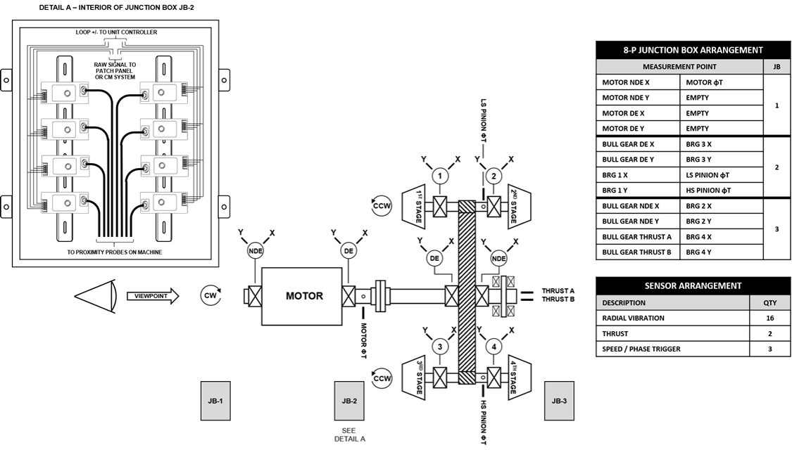
Figure 16 – Typical System Arrangement for API 672 Air Compressor using MX2034 Proximity Transmitters

Figure 17 – Typical System Arrangement for API 617 Process Compressor using the SW5580 two-channel monitor.

Download our Integrally Geared Centrifugal Compressor Monitoring Whitepaper