
Vibration Monitoring of Cooling Towers
A cooling tower utilizes the evaporation of the cooling liquid to dissipate heat. Generally, a cooling tower has nozzles that let the cooling liquid fall into open air. The liquid is released at the top of the tower and cascades down across a series of ventilated shelves. A fan at the top of the tower draws fresh air through the ventilated shelves and across the falling water. The air cools the liquid, which is then collected, filtered, and returned to the delivery system to gather more heat.
Applications
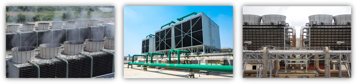
Cooling towers are commonly used in petroleum refineries, power generation plants, natural gas processing plants, petrochemical plants, and other industrial processing facilities. Cooling towers act as a special type of heat exchanger that cools down water heated up by industrial equipment and processes. In the cooling tower, heat is rejected from the working fluid (water) into the atmosphere (air) by means of evaporation (wet) and convection (dry) cooling.

Download our Vibration Monitoring of Cooling Towers Whitepaper Download our Vibration Monitoring of Cooling Towers Brochure
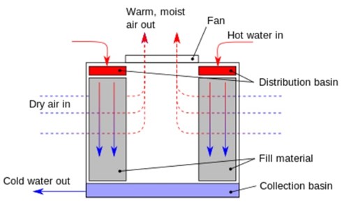
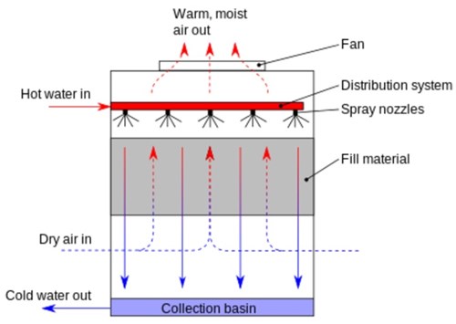
For evaporative cooling towers, hot water from an industrial process is pumped up to the top of the cooling tower, then gets distributed to the wet deck, and then flows down through the fill material (lattice structure). At the same time, air is being drawn through the air-inlet louvers forcing water to evaporate. Evaporation causes the heat to be removed. Finally, cold water circulates back into the industrial process. With respect to the air-to-water flow pattern, cooling towers can be categorized into two families: cross-flow cooling towers and counterflow cooling towers. Their diagrams are shown below.
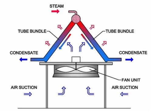
In the dry cooling tower there is no evaporation in the process. The hot working fluid flows inside the tube bundles. The tube bundles have a very large convection surface area. The lower temperature ambient air flow is blown from outside tube bundles. As a result, the hot fluid is cooled. The diagram is shown below.
Primarily airflow can be driven by either natural draft or induced / forced draft in cooling towers. In natural draft, air flow occurs because of the temperature gradient from the cool bottom to the hot top of the cooling tower. On the other hand, induced draft systems use fans at the top discharge area to pull air up through the tower and forced draft systems use fans at air intake louvers to push the air into the tower.
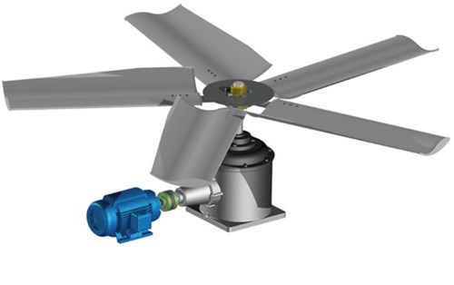
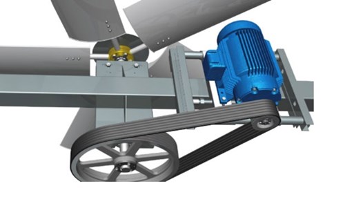
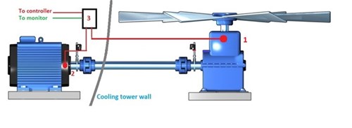
In induced / forced draft cooling towers, fans play a critical role in the air circulation. Two types of cooling tower fan drive designs are commonly used, gearbox driven fans and belt driven fans. A gearbox driven fan has the motor mounted to the side of the fan’s cell and drives the fan using a shaft. In the belt driven fan case, a motor drives the fan using a belt. A belt driven fan is typically used in smaller cooling towers while the gearbox driven fan can be used in larger towers. The difference of these two types of fans can be seen from the following graphics.
Failures and Causes
Catastrophic failure of a cooling tower can bring serious consequences to plant business operations, such as failure of other equipment, safety hazards, downtime, lost production revenue, expensive repairs, and health issues. Common causes of failure in cooling tower components can often be linked to either the misalignment or imbalance of components. Studies have shown that the most common failures in cooling tower components were related to the motor (60%), the gearbox (30%), the fan (2%) and others (8%). More specifically, the failures of a motor can be caused by motor imbalance, shaft misalignment, rotor bar defects, bearing defects, and improper foundation mounting. Gearbox failure causes include the result of stress from being in the airflow of the cooling tower, misalignment of the gear with the motor, added stress to the gear teeth and bearing failures. Fan failures can be the result of unbalanced fan blades, or changes, or errors, in blade pitch.
Assets Protection
As the cooling tower failure consequences are understood and the causes of failures are analyzed, priority to prevent the catastrophic disaster occurs, which leads to asset protection. Measuring the key vibration parameters and analyzing vibration data from a cooling tower are the most important actions to be taken.
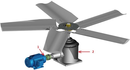
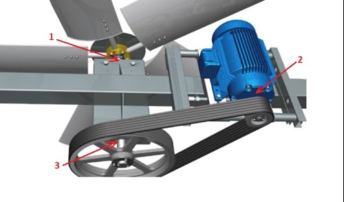
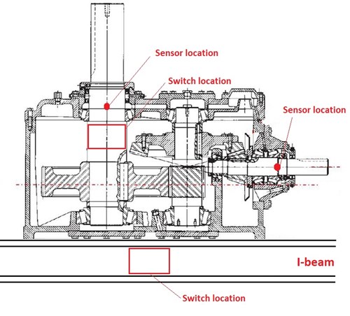
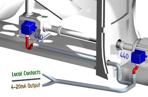
The OEM recommends installing at least one vibration sensor on the gearbox and /or fan bearing. The sensor installation positions are illustrated in the above graphs and described as following:
To collect vibration data on gearbox driven fans, one has to monitor both the motor and the gearbox. To collect vibration data on belt driven fans, one must monitor the fan inboard pillow block bearing, the motor inboard bearing, and intermediary bearings on the fan shaft.
In general, most cooling tower fans run at a speed somewhere between 90 and 300 revolutions per minute (rpm) while motors for cooling towers generally run at speeds around 1,500 to 1,800 rpm. Two organizations have developed vibration standards for cooling tower fans. The Cooling Technology Institute (CTI) Vibration Standards are presented in units of displacement (mils pk-pk, μm pk-pk) and are dependent on both construction type (steel, fiberglass, wood, or concrete) and frequency. No overall vibration standards are given by CTI. The Technical Associates (TA) Machine Specific Standards concern overall vibration levels and are dependent on the drive type (close coupled direct drive, close coupled belt drive, or long hollow drive shaft). The TA Standards are presented in units of velocity (ips-pk, mm/s-pk).
Metrix Products
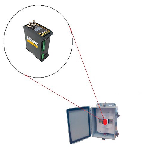
Metrix offers a complete solution for vibration measurement and machine protection.
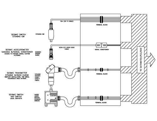
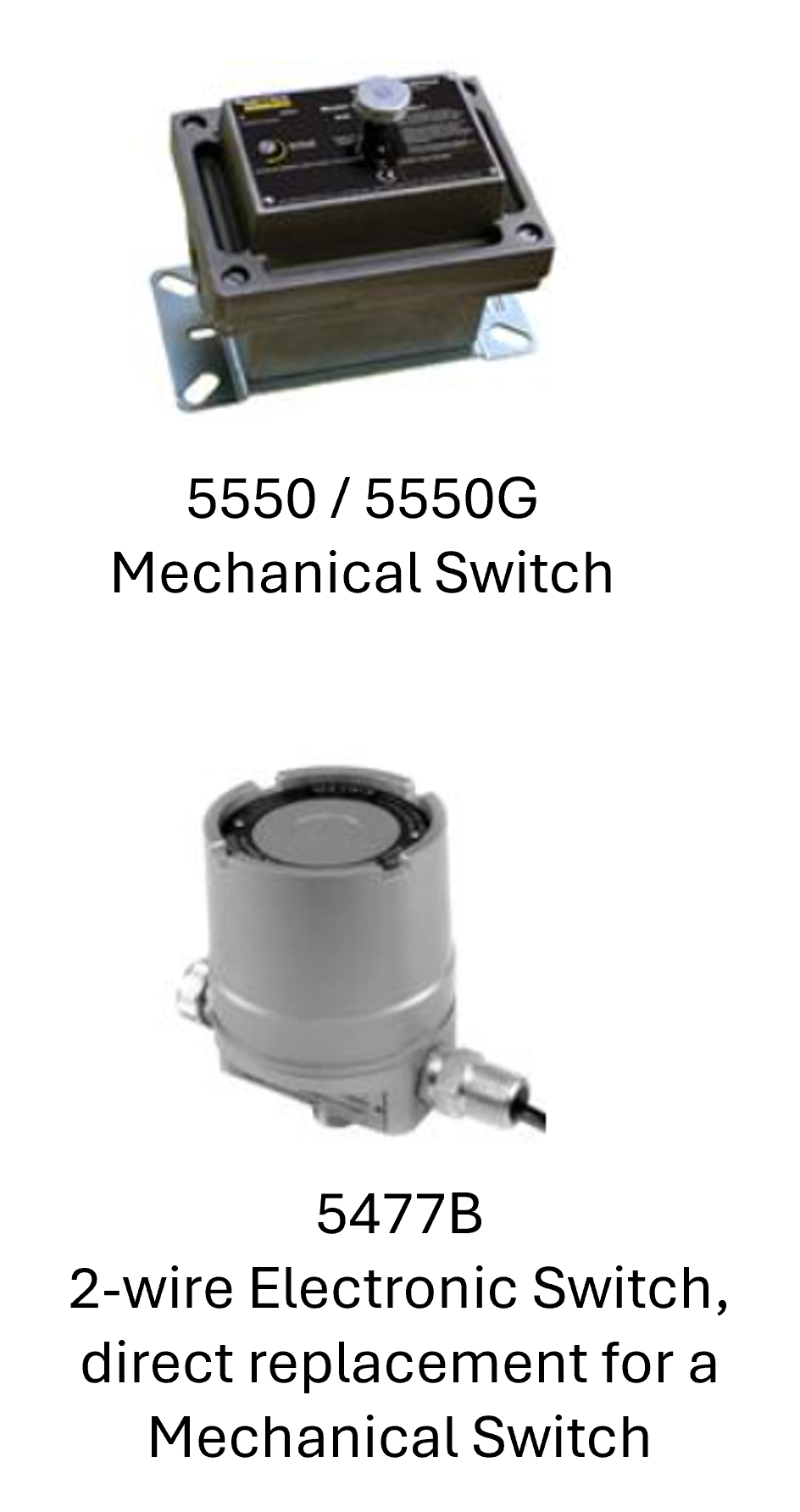
As the most basic form of protection, Metrix offers cost effective mechanical switches such as the 5550 / 5550G. It provides vibration protection for low to medium speed machinery. The 5550/5550G mechanical vibration switch contacts can be used to activate an alarm or initiate equipment shutdown.
We also have a variety of electronic switches which not only provide basic protection but also increased sensitivity and accuracy.
If you have been thinking about upgrading your mechanical switch to an electronic switch, but the cost of adding additional wiring for an electronic switch is an issue, then our 5477B Electronic Switch is an ideal replacement. It features two-wire hookup and solid-state reliability.
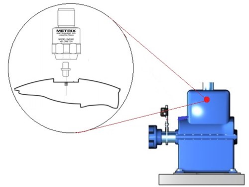
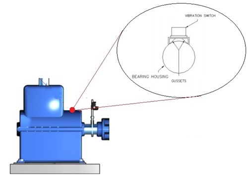
For cooling tower applications, the primary mounting locations for vibration sensor / switch and monitor / control instruments are shown below.
Basic Mounting Concept:
- Sensors (SA6200A) should always be mounted in line with the rolling element bearings on the case of the machine.
- For switches with internal sensors we recommend monitoring overall movement of the assembly, not specifically bearing location.
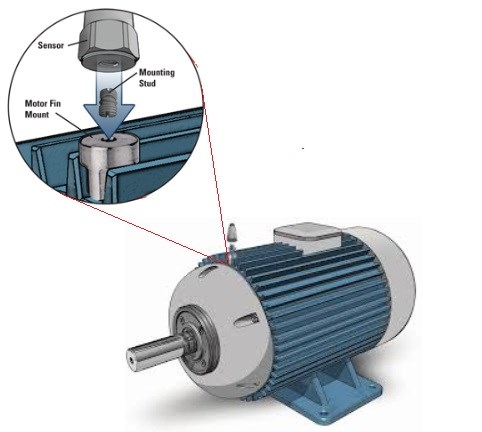
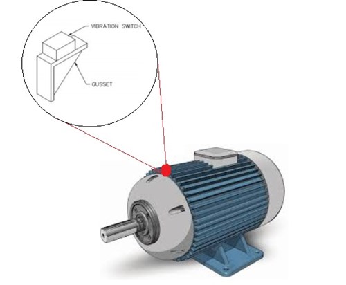
Mounting Method
Stud Mounting
Gusset Mounting
DIN Rail Racking Mounting
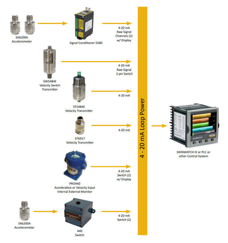
Monitoring Solutions
Metrix has a broad range of product options to meet various cooling tower applications. Select one of the following system solutions that works best for your application.
 |
 |
|
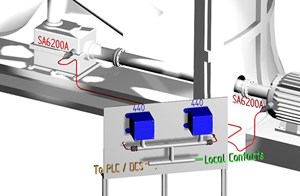
440 Internal Sensor
|
440 External Sensor |
|
 |
 |
|
|
5580 Signal Conditioner
|
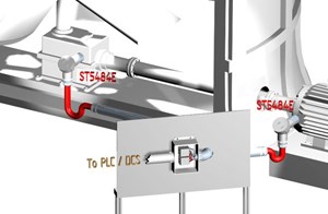
ST5484E Velocity Transmitter |
|
 |
 |
|
|
5550/5550G Mechanical Vibration Switch 5550 and 5550G mechanical vibration switches provide basic, economical vibration protection by means of a simple and highly reliable “over center” snap action mass and spring mechanism. |
5477B Two-Wire Solid State Switch The Model 5477B switch features two-wire hookup and solid-state reliability. This makes it an ideal replacement for mechanical vibration switches when increased accuracy and repeatability are required. |
![]()