
Reciprocating Compressor Monitoring with the Metrix MX5000
Overview
This whitepaper examines the basis for condition monitoring on reciprocating compressors (hereafter referred to as simply “recips”), the classes of recips most often receiving condition monitoring, the need for more cost-effective solutions on a broader range of recip classifications, the suite of measurements recommended for adequate monitoring of the most common recip failure mechanisms, and the ways in which the Metrix MX5000 Vibration Monitoring System (VMS) has been designed to economically address such applications.
Suitable Solutions
The MX5000 product family was introduced to provide a monitoring and protection system for necessary recip measurements in an affordable, robust industrial package, suitable for the global hazardous area classifications commonly encountered with recip instrumentation.
Where competing solutions are aimed primarily at API 618-class machines, the MX5000 concerns itself with the remaining reciprocating machines at industrial facilities and does so by reducing the cost of monitoring per throw by a factor of ten.
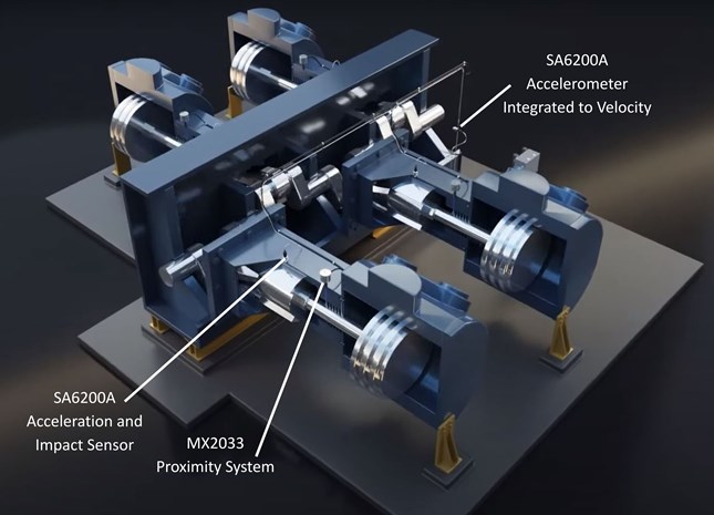
Figure 1 – 4 Throw Reciprocating Compressor
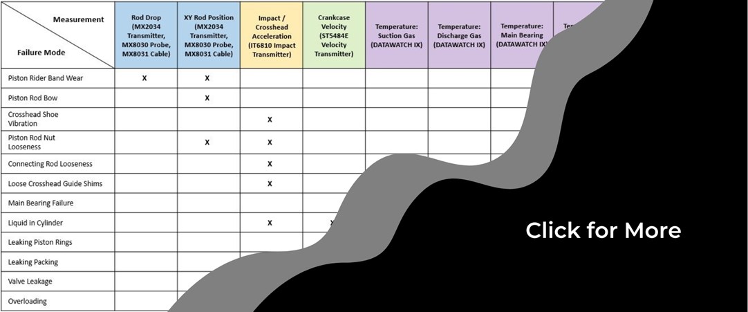
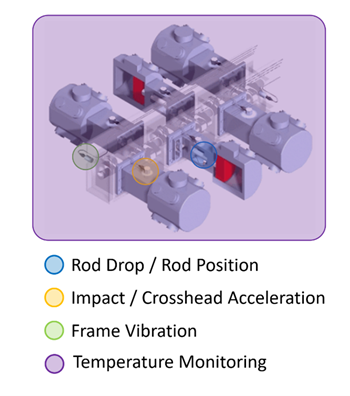
Figure 2 – Failure modes and corresponding measurements for reciprocating compressors
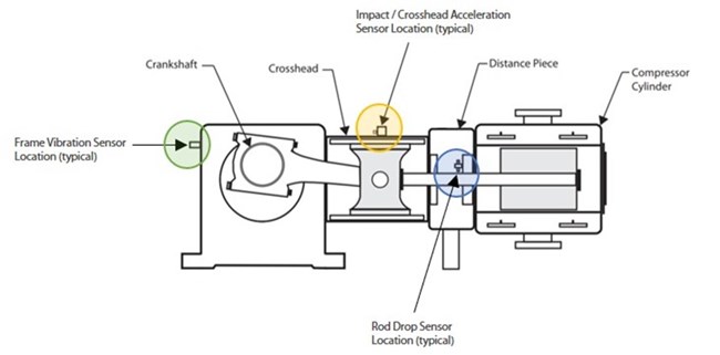
Figure 3 – Recommended Reciprocating Compressor Measurements and Locations
Where it is not unusual to instrument 618 machines at costs exceeding $100,000 per throw, operators of other reciprocating machines are looking for capable and reliable monitoring on the order of $10,000 per throw. The MX5000 has been designed with this price point in mind and reflects a total installation cost of approximately $1,000 per measurement point or less than $6,000 per throw for an adequately instrumented reciprocating machine compared with $100,000 per throw for an adequately instrumented 618-class compressor. The suite of measurements recommended by Metrix on reciprocating compressors reflects experience gathered over several decades and this suite has shown to be adequate for detecting the most common malfunctions and maintenance-intensive aspects of the machine.
Figure 2 summarizes these measurements and corresponding malfunctions detected. Figure 3 provides additional mounting location details.
Later in this document, the attributes, features, and functions of the MX5000 will be discussed in detail. Next, however, the measurements themselves are described along with their purpose.
Recip Measurements
The MX5000 SIM (Sensor Interface Module) can be used to monitor frame vibration, rod drop or rod position, impact and crosshead acceleration and other necessary parameters. The SIM is a 4-channel module that can standalone or be coupled with up to 5 other SIM modules for a total of 24 channels (See Figure 4).
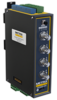
Figure 4 – MX5000 SIM (Sensor Interface Module)
Frame Vibration
Frame vibration (sometimes called crankcase velocity) is simply the overall vibration amplitude of the compressor frame. It is one of the most fundamental recip measurements and does not require special signal conditioning other than basic low-pass and high-pass filtering and signal integration (if the sensor does not provide a native velocity output). Frame vibration is typically measured at two horizontal locations (each end of the frame). The horizontal mounting axis is chosen because the horizontal direction of the machine is usually the most compliant (i.e., least stiff). This measurement is useful for monitoring abnormalities that occur at or near the running speed of the machine and manifest as high casing vibration. Examples of such problems may include degradation of the machine’s foundation, mechanical imbalance, or imbalance due to abnormal gas forces. Abnormalities in the running gear can also frequently manifest as elevated frame vibration.
The measurement is made with a conventional accelerometer (integrated to velocity units at the monitor) or with a sensor providing a native velocity output such as the Metrix SV6300 (piezo-velocity) sensor.
Average Rod Drop
Rod drop is a measurement intended for horizontal cylinders with pistons utilizing non-metallic rider bands. As the rider bands wear, the gap between the piston and the bottom of the cylinder wall will decrease and the piston rod will exhibit a corresponding vertical drop in its average position. By mounting an eddy-current proximity probe vertically on the pressure packing case to observe the piston rod, this drop can be measured as a change in average gap (i.e. DC gap voltage) and using the geometry of the machine, the amount of drop in the rod can be translated to the amount of rider band wear. Alarms can be set to notify operators and machinery personnel that it is time to replace the rider band(s). The probe can be mounted above or below the rod to observe this drop, but care must be taken to ensure probes mounted above the rod will remain within their usable linear range as the rod drops. For this reason, extended range probes (11mm tip diameter, or Metrix 8mm Extended Range feature) with 180 mils (4500 µm) of usable range are often selected.
It’s important to understand that the rod drop measurement is intended to measure rider band wear. Metrix recommends recording data, at least hourly, and taking a 7-day running average to smooth out the readings and provide a better measurement of the actual wear taking place at the rider bands.
It should be noted that not all reciprocating compressors are necessarily good candidates for rod drop measurements. Characteristics that comprise the rod drop measurement include, but are not limited to:
- Non-lubricated cylinders
- Compressors with running speeds in excess of 1800 rpm
- Compressors with excessive flexing of piston rods; this can occur when the rod is too long relative to its girth and exhibits excessive flexure during the stroke, resulting in erratic measurements. A good rule of thumb is that the length of the piston rod should generally be no more than 25 times larger than the diameter of the piston rod.
- Other factors can also affect the efficacy of rod drop measurements as the above list does not comprise all relevant considerations. Contact the Metrix factory for a detailed application review before concluding that rod drop measurements will give satisfactory performance for your machine.
If desired, a supplementary probe can also be mounted in the horizontal direction for additional diagnostic information on piston rod movement. This is depicted in Figure 5.
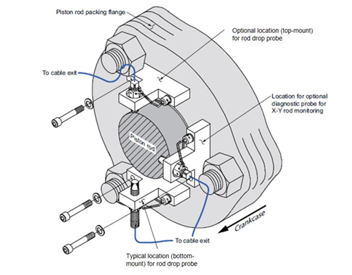
Figure 5 – Typical Rod Drop Probe Mounting Arrangement
Impact
The impact transmitter was pioneered by Metrix in 2001 and a US patent awarded in 2003. Impact has proven to be a remarkably effective measurement in the intervening two decades and many customers have adopted it so readily that they will not run their compressors without it. The concept is quite simple: by placing an accelerometer on the crosshead of each throw, looseness and other malfunctions in the running gear can manifest as mechanical impacts that excite resonances in the structure. Examples of malfunctions resulting in impacts include liquid in cylinders, excessive clearance in crosshead pin bushings, and loose or cracked nuts / cylinder liners / pistons.
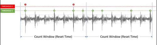
Figure 6 – Impact Measurements
The time waveform of these measurements exhibits a ringing and decay as the resonance is excited during each impact (Figure 6). The number of impacts over a set period of time known as the “count window” or “reset time” is tallied. Once the time established for the count window has elapsed, typically 16 cycles of the reciprocating compressor, the MX5000 returns the number of impacts and then begins counting again. By trending this number, changes can be observed and alarms established to signify problems.
The period over which impacts are counted is usually selected to correspond to approximately 16 crank revolutions. For example, if a machine runs at 400 rpm, 16 crank revolutions span 2.4 seconds and the reset time (count window) would be set accordingly as 2.4 seconds.
It is important to note that the absolute number of impacts occurring within the count window is not as important as the observable trend over minutes, hours, days, or longer. It is this trend that conveys the onset and growth of problems. The impact measurement has no associated engineering units. It is simply a count of events expressed as an integer value between 0 and 16. If more than 16 impacts occur during the count window, this generally means the threshold has been set too low or the impact has progressed to levels that require analysis and maintenance intervention. When set up correctly, impacts of 8 or more are used to initiate closer inspection, impacts of 12 or more usually indicate the machine should be shut down and inspected.
Referring again to Figure 6, using threshold 1 (green) would result in four impacts during the first and second count windows. Using threshold 2 (red) instead would yield two impacts during the first count window and no impacts during the second count window.
Please note that Figure 6 is intended to convey the basic concept of impact measurements, threshold settings, and count window duration. It is not intended to serve as a comprehensive how-to guide for setting an appropriate threshold. For a more exhaustive and detailed treatment on establishing appropriate threshold level for impact measurements, refer to the installation manual for the MX5000.
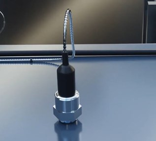
Figure 7 – Metrix Impact Measurement SA6200A Accelerometer Mounted on a Reciprocating Compressor Crosshead
While the Metrix impact transmitter (IT68XX) introduced an economical and effective means of monitoring numerous running gear issues on reciprocating compressors, its design suffers one drawback: it is cumbersome to adjust because the threshold and reset time settings are made on the transmitter itself. Using the MX5000, in combination with the SA6200A Accelerometer mounted on the crosshead (see Figure 7), makes the impact measurement setup very easy.
Impact monitoring via the MX5000 is a dramatic improvement. First, it makes use of a standard accelerometer rather than a specialized transmitter for this measurement. The sensor type is less expensive and may be used elsewhere on the machine or in the plant for reduced spare parts requirements. Second, this arrangement places adjustment of threshold and count window settings in the MX5000 itself – not the sensor. It thus removes service personnel from the machine location when configuring and making adjustments to the measurement chain and places them in a more suitable environment.
Crosshead Acceleration
Closely related to the impact measurement is the crosshead acceleration measurement. This measurement uses the same accelerometer as that used for the impact measurement, but instead of counting impacts, it simply measures the 0-pk amplitude of the raw acceleration signal. It thus becomes a so-called “dual path” measurement where a single sensor goes through two signal processing paths: one to return impact counts and one to return the amplitude of the vibratory acceleration signal. This acceleration signal is useful for both alarming purposes and trending, and as a rich source of diagnostic information when connected to a suitable handheld analyzer. While changes in impact counts signify something is malfunctioning, analysis of the raw acceleration signal yields insight into what is malfunctioning. A general rule-of-thumb is that no single crosshead should exhibit markedly more (i.e., twice as much) vibration than the others.
Vibration and Axial Position on Drivers
Many recips are electric motor driven. For those with rolling element bearings, an accelerometer or piezo-velocity sensor is often mounted on each bearing cap and brought into the MX5000 as a seismic bearing vibration measurement. For drivers utilizing fluid-film bearings (whether electric motors, steam turbines, or others), proximity probes are used instead and are also compatible with the MX5000 for both radial (shaft-relative vibration) and axial (thrust) measurements. As with all other measurements, alarms can be set for each channel of the MX5000 and a 4-20mA output, as well as a Modbus output, sent to a PLC, DCS, or other machine control platform for trending and display as part of an integrated machine control and monitoring environment.
Rotative Speed
While most machines will already have a speed measurement available, in the event one is not available, or a local display of speed is desired, the MX5000 can be configured to display rotative speed from a proximity probe observing a toothed surface or a key / keyway. A once per turn phase trigger is necessary for instantaneous rod drop measurements.
Temperature
- A variety of temperatures are useful for monitoring reciprocating compressor health. These include but are not limited to:
- Suction gas temperature
- Suction valve temperature
- Discharge gas temperature
- Discharge valve temperature
- Pressure packing case temperature
- Main bearing temperature
Motor winding temperatures (usually six total: 2 TCs or 2 RTDs per winding on all three phases)
Most PLCs, DCSs, and machine control and automation platforms have suitable I/O modules to directly accept Resistance Temperature Detectors (RTDs) and/or thermocouples (TCs). In the event that a control or automation platform cannot be used, the MX5000 TIM (Temperature Interface Module – Figure 8) should be used. It provides 8 channels of temperature monitoring per TIM module.
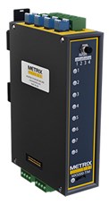
Figure 8 – MX5000 TIM
The MX5000 can have up to 7 TIMs or 56 channels of either thermocouple or RTDs. A TIM can stand alone or be connected to 6 other TIMs. The TIM comes complete with alarms, relay outputs, and Modbus digital communications for 8 to 56 inputs. Each TIM module also has 4-20 mA outputs for each channel.
Shutdown Versus Alarming Considerations
Two levels of setpoints are available in the MX5000: Alert (pre-shutdown) and Danger (shutdown). Where alarm settings are available from the OEM, those levels should be implemented by default and then adjusted over time as process, operating conditions, and experience dictate. Although there can be numerous vibration, position, and temperature measurements associated with reciprocating compressors, most industry standards suggest that only a small number be used for machinery protection (i.e. auto-shutdown) purposes with the rest being used for condition monitoring purposes. Most of the measurements discussed in this application note are suitable for both machinery protection purposes and condition monitoring purposes: frame vibration, crosshead acceleration, impact, rod drop, and vibration / position on the driven machine.
For measurements where proximity probes are used, whether rod drop on the compressor, axial position on the driver, or radial vibration on the driver, alarm setpoints are established based on the physical clearances in the bearings between shaft and bearing pads or the clearance between piston and cylinder wall liner provided by rider bands.
In contrast, alarm limits from seismic transducers on the compressor do not derive from physical clearances and geometries of the machine but rather empirical data collected over time to distinguish normal operation from abnormal operation. Operators and maintenance personnel will quickly lose confidence in a system that generates spurious alarms, particularly when subsequent inspection shows no observable machine distress or damage.
Many temperature measurements are intended for auto-shutdown purposes, such as bearing temperatures, motor winding temperatures, lube oil temperatures (and pressures), and gas discharge temperatures. However, the control system for the compressor and its driver will often incorporate these critical temperature and pressure measurements as shutdown parameters. Examples include loss of lube oil pressure or excessive gas discharge temperature. For this reason, users will most often be dealing with vibration, position, and temperature measurements that did not come as part of the base control and protective package supplied by the compressor OEM. Valve temperature monitoring is one such example. It is not used for protective purposes and is instead used to indicate that the condition of one valve within a suction or discharge group is markedly different than its peers. As such, the valve temperature measurement computes the average temperature for a group of valves and alarms on the differential between any single valve and this average. This can routinely be accomplished in the PLC or DCS.
Cylinder Performance Measurements
While the critical role that API 618 machines often play in a plant’s production process justify the addition of cylinder pressure sensors and precision speed wheels for triggering measurements based on crank position to give rod load, rod reversal, and so-called PV (Pressure-Volume) curves as part of comprehensive cylinder performance monitoring, this level of condition monitoring is rarely warranted on less-critical classes of reciprocating compressors. Indeed, one of the primary distinctions between these reciprocating compressors and those for which the MX5000 are intended is that such machines cannot justify the additional expense of continuous PV monitoring.
MX5000 Vibration Monitoring System
The Metrix MX5000 is designed to cost-effectively address machinery that does not warrant the cost and complexity of a system with all the features and functions required by API 618. It is a right-sized solution for such machinery and offers an appropriate feature set.
The following features make the devices appropriate for monitoring a wide variety of machinery employing both fluid-film and rolling element bearing types:
Integral Alarming / Relays
The MX5000 has integral alarming capabilities and solid-state relays in each SIM and electromechanical relays in the REM to externally annunciate and transmit these alarms for indication and machinery protection (i.e. auto-shutdown) purposes.
Universally Configurable Design
Prior generations of Metrix signal conditioners and switches consisted of different models for different measurements. One model was required for radial vibration measurements, another for axial position or rod drop measurements, another for impact measurements, another for speed, etc. Like, the Metrix two-channel 5580 / SW5580, the MX5000 uses a fully software configurable design that allows it to be configured for any vibration measurement and 4-20 mA process variable measurement. This reduces personnel training costs and spare parts burdens. It also ensures that changes to measurements can be made entirely via software, in the comfort and safety of an office environment, and then the device can be installed in the field.
Sensor Interface Module (SIM)
Prior Metrix signal conditioners and switches were single channel designs. With the advent of the 5580 and SW5580, the two-channel system made monitoring easier. The MX5000 provides an independently configurable 4-channel device that can be stacked together to create a 24-channel vibration monitoring system. For example, one channel can accept a seismic sensor for impact monitoring, and the other channel can be a proximity probe for rod drop measurements. The device can also be configured for so-called “dual-path” monitoring whereby a single sensor is processed in two separate paths to provide two separate measurements. One of the measurements can be chosen to go to the 4-20 mA output, but both measurements can be sent out via Modbus. For example, a single accelerometer mounted on a compressor throw’s crosshead can return the raw crosshead acceleration amplitude, as well as impact counts. One of these, either acceleration or impact, can be indicated on the 4-20 mA output, but both measurements can be output via Modbus. Another example is a single proximity sensor monitoring piston rod position and vibration. Although the measurements share a common sensor, the signal processing, measurement types, and alarm setpoints are independent of one another, and again one of the measurements, either rod drop or rod vibration, can be selected to be the 4-20 mA output, or both measurements can be output via Modbus.
Multi-State LEDs on Each SIM
Alarm and status conditions are clearly annunciated at the device via multi-state LEDs as follows:
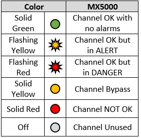
There is one LED for each channel, allowing separate and unambiguous status annunciation for each measurement and sensor.
SIM Universal Inputs
The MX5000 SIM supports most commercially available acceleration, velocity, proximity sensors, and 4-20 variable process sensors. Each channel includes the provision of providing necessary sensor power. A single +24Vdc connection powers the device, its 4-20mA output(s), and its connected sensor(s) – including the -24Vdc power required by proximity transducers and the constant current required by IEPE accelerometers and piezo-velocity sensors.
Each SIM channel can be uniquely configured using the configuration and display software. If required, each SIM can be ordered with Hazardous area certification (Class 1 Div 2, Zone 2). Each SIM is SIL 2 capable.
Individual, Configurable Relays
For each SIM model, four (4) relays are provided. Each channel can be mapped to any of the four relays. This allows ALERT and DANGER to be separately annunciated for each channel. The relays can be configured for latching or non-latching operation, normally energized or normally de-energized. Normally Open (N.O.) and Normally Closed (N.C.) wiring terminals are provided. The SIM relays are solid-state (SPST) relays. If electromechanical (SPDT) relays are needed, then the SIM must be paired with a Rack Emulation Module (REM). Solid-state relays are typically used for providing logic-level alarm status to controllers and other devices.
Electromechanical relays are typically used to switch interposing relays, fuel valve solenoids, or other trip devices as part of the machine’s control where the signal being switched is larger than a logic-level voltage.
Local Buffered Outputs
Conventional BNC connectors for each channel are provided for easy connection to portable instruments such as data collectors, DVMs, and analyzers where the cable length does not exceed 16 feet (5 meters). These outputs are isolated from the 4-20mA outputs to ensure connection of external devices does not compromise the integrity of the monitoring or protective functions.
Amplified Buffered Outputs
When devices are mounted in junction boxes at the machine, it can be inconvenient to open the box to connect portable instruments. In prior generations of Metrix devices, and on most commercially available monitors, the buffered outputs are not suitable for wiring runs exceeding 5-10 meters without use of an external amplifier to drive the raw signals over long distances. The MX5000 overcomes this limitation by employing integrated signal amplification, allowing buffered output signals to be driven up to 1000 feet (300 meters). The amplified signal is available at wiring terminals and is intended for permanent connection to remote patch panels or other Condition Monitoring Systems (CMS).
Modbus Output
The RJ45 connector on the SIM allows RS485 communications with a control system. All the values created by each of the channels can be output via a Modbus. This includes overall values, Alert and Danger alarm status, bypass status, Channel OK, and other configured values.
Temperature Interface Module (TIM)
The Temperature Interface Module (TIM) can stand alone or be paired with additional SIMs and TIMs for up to seven modules or 56 channels of temperature monitoring in each system. Each TIM is an 8-channel temperature monitor capable of taking inputs from Resistance Temperature Detectors (RTD) or Thermal Couples (TC). Like the SIM, the TIM is powered by 24-volt DC power. If TIMs are put with other SIMs or other TIMs, power only needs to go into one of the devices and the power is shared. Redundant power supplies are allowed by simply putting a different 24-volt DC source into one of the adjoining SIMs or TIMs. Similar to the SIM, each TIM has a 4-20 mA output for each channel, as well as a Modbus RS485 output. Each TIM has four solid-state relays that can be mapped to one or more of the channels in the module or connecting modules. Each TIM channel can be uniquely configured using the configuration and display software. If required, each TIM can be ordered with Hazardous area certification (Class 1 Div 2, Zone 2). Each TIM is SIL 2 capable.
Rack Emulation Module (REM)
The Rack Emulation Module creates the features required for a Machinery Protection System (MPS) that meets the requirements of API 670. The REM includes the communication module, electromechanical relay module, configuration module, system fault and bypass circuits, real time clock and event list, and the power supply module.
REM Features:
Module provides primary or backup power to the other connected modules – 21 to 30 Vdc (24 Vdc nominal - allows for redundant power supplies).
The System Configuration Port allows a PC to connect to the REM unit to configure the entire system (including each module) – The REM is password protected.
Relay Configuration
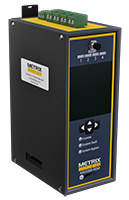 Figure 9 – MX5000 REM
Four (4) Epoxy Sealed, Single-Pole Double-Throw (SPDT) Electromechanical Relays are included in each REM. These relays support an AC voltage range of 5-250 Vac for loads of 100 mA to 4 A. The relays also support DC voltages and loads of 5-30 Vdc at 4 A. Relays can be individually configured for single or dual (2 out of 2 voting or 1 out of 2 voting). For 2 out of 2 voting there will be an option to go to 1 out of 2 voting on transducer Not OK or Channel Bypass. Any SIM or TIM channel can be used in the voting logic.
REM LCD Display
The display shows information for one channel at a time. The select button will advance up or down through the channel list. Each Channel will be identified by module number and channel number (e.g. SIM 1 CH 1). The display will show the outputs of the channel, the alarm status, as well as OK and Bypass status.
Auxiliary Contacts
There are common relay contacts that indicate if any channel is in Bypass, and if any channel or system is NOT OK.
There is a Trip Multiply feature that can be activated locally or remotely. Remote activation can be via digital communications or a contact closure on the REM. The Trip Multiply value is configured in each channel.
Another set of contacts is included for local and remote Reset. Remote Reset is by terminal contacts or digital communication.
Self-Test and Test Modes
There is an on-board self-test with indication of system status. One can test all indicators by holding the Reset button down for 10 seconds.
The REM will be capable of a “TEST MODE” where a user can drive output values via the configuration software for testing purposes.
Real-Time Clock and Event List
The REM has a real time clock that can be set via configuration or from another device via Modbus. The REM will keep a System Event List of Alarms, Bypass, Transducer Not Ok, and System Faults that are timestamped and accessible via an HMI or Display software. The Event List is in time order (i.e. indication of “first out” Alert and Danger).
Modbus TCP/IP Connection
Modbus over Ethernet is available for connection to other Human Machine Interfaces (HMI’s), unit control systems, and other plant automation equipment. The module can be configured as a server and supports configurable Modbus addresses.
Phase Trigger
A phase trigger can be created by any SIM Channel and is sent to other SIM Channels to obtain necessary phase and speed information required of the MPS.
The two-phase trigger lines run through the SIM(s) and TIM(s) to provide the phase trigger signals to the REM.
As many as two Phase Triggers can be assigned per system (only one Phase trigger can be generated per SIM).
Four analog lines run through the SIM(s) and TIM(s) to the REM to provide dynamic signals that are the equivalent of the buffered output signals.
REM Modbus Outputs
The REM can provide the following static values or outputs via Modbus TCP/IP:
- Overall Amplitude
- Alarm Status and Notifications
- Gap Voltage (Proximity Sensor)
- Bandpass Frequency Band Amplitude
- Speed (RPM)
- Process Variable (e.g. given a 4-20 mA Input: Pressure, Temperature, Flow, Level, Valve Position, Custom)
- Impact
- Rod Drop
- Rod Position
- Reverse Rotation
- Zero Speed
NOT OK Annunciation
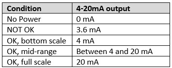
In addition to NOT OK status annunciation via the device’s LEDs, the current loop (4-20mA) output for each channel will clamp to a value below 4mA, ensuring that a NOT OK condition can be distinguished from other conditions.
DIN-Rail Mounting
Each MX5000 is mounted on standard 35mm DIN rail and uses an integral rail mounting clip. The 20-pin connector between modules creates a “backplane” that integrates the entire MX5000 System together.
Hazardous Area Approvals
The devices carry North American (CSA), European (ATEX), and Global (IECEx) hazardous area approvals, allowing them to be mounted in Class 1 Division 2 / Zone 2 environments. Refer to Metrix drawings in the MX5000-SIM Installation Manual (Doc# 1992489). When the machine itself is in a Div 1 or Zone 0/1 environment, active or passive intrinsic safety barriers may be placed between the sensor and the MX5000 to satisfy hazardous area approval criteria. The MX5000 and corresponding I.S. barriers must be in a Div 2, Zone 2, or non-classified area. See the specific sensor drawing for I.S. barriers.
Typical System Arrangement
Figure 10 on the following page depicts a typical system arrangement for an electric motor driven 4-throw compressor comprising the following measurements:
- Rod Drop for each throw (4)
- Crosshead acceleration and Impact for each throw (4)
- Frame Vibration (inboard and outboard) for the compressor frame (2)
- Motor bearing vibration (inboard and outboard) on motor (4)
- Motor speed (1)
Power Supply Considerations
A 24Vdc power supply can be selected from any reputable provider and for added reliability, redundant schemes can be used if desired. When selecting a power supply, use the following sizing considerations for each MX5000.
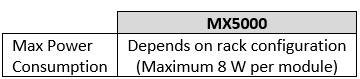
The table above assumes worst-case conditions where all relays are energized, all transducers are proximity probes consuming maximum power of 12mA at 24V, all recorder outputs are at full scale of 20 mA, and all buffered outputs are driving the maximum allowable length of field wiring at maximum signal amplitude.
Enclosure Considerations
When mounting the system at the machine, a suitable enclosure is required to protect the electronics from the elements. Additionally, an enclosure may be mandatory for installation in NRTL Class 1 Div 2, IECEx and ATEX Zone 2 hazardous environments. Where local display of status and current values is required, choose a suitable PC panel display for the HMI.
When sizing the enclosure, refer to the MX5000 datasheet (Doc# 1986617) for heat dissipation requirements to ensure adequate airflow and that temperature rise does not subject the devices to operation outside of maximum ratings. Make certain to include the power supply in these calculations as well. Consult the factory or your local Metrix sales professional for assistance, including installation and project advice.
Figure 10 – 4 Throw Reciprocating Compressor
Typical System Configuration for a Motor-Driven 4 Throw Reciprocating Compressor:
• 4 Crosshead Impact Sensors (Accelerometers)
• 4 Rod Drop / Vibration Sensors (Proximity)
• 2 Crankcase Sensors (Velocity)
• 4 Motor Vibration Sensors
• 1 Motor Speed Sensor
• 4 Cylinder Outlet Temps (TC or RTD)
• 4 Motor Temp Sensors (TC or RTD)
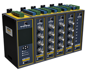
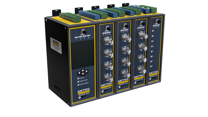
Figure 11 - 3D Picture of MX5000 – REM, 4 SIMs and a TIM

Download our Reciprocating Compressor Monitoring with the Metrix MX5000 Whitepaper