
MX5000 Monitoring of Turbine Driven Compressors
Compressor Reliability and Condition Monitoring
Overview
Turbine driven compressors are among the most critical rotating machines in oil and gas production, LNG facilities, petrochemical plants, refineries, and pipeline transmission systems. These machines are responsible for compressing and transporting gas to sustain continuous production, meet contractual delivery requirements, and maintain safe operating conditions.
A turbine driven compressor train typically consists of a gas or steam turbine driver, high-performance flexible coupling, and a multi-stage centrifugal compressor. If a gas turbine is used, the gas turbine itself is a turbine driven compressor. The turbine driven compressors that we discuss in this paper are monitored in a very similar way. These high-speed rotating assemblies often operate above 5,000 RPM and may exceed 15,000 RPM depending on application.
Most large centrifugal compressors utilize fluid film journal and thrust bearings. These bearings depend on a continuous oil film to support the shaft and prevent metal-to-metal contact. Due to high speeds, tight clearances, and stored rotational energy, any instability or malfunction can rapidly escalate into a catastrophic failure.
Reliable condition monitoring for both the rotor and the casing of both the turbine and compressor is essential to protect the machine, personnel, and production.
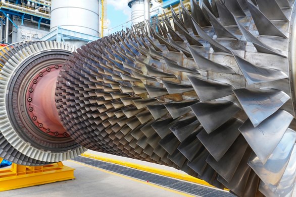
Turbine Driven Compressor Rotor
Common Malfunctions
Unbalance
Occurs when the rotor mass centerline does not coincide with the rotational centerline. In compressors, unbalance may result from fouling, erosion, blade damage, or coupling issues. In the turbine, unbalance may be due to corrosion, blade damage, or uneven heating of the rotor caused by a seal rub. This unbalance produces elevated 1× running speed vibration.
Misalignment
Results when the turbine and compressor shaft centerlines are not collinear. Usually the high-performance coupling mitigates minor misalignment between the turbine driver and the compressor. When the misalignment is significant, the flexible coupling cannot compensate, resulting in axial and radial vibration, coupling wear, and elevated thrust loads.
Rotor to Stator Rubs
Rotor to stator rubs can occur in the turbine or the compressor, and are usually due to misalignment between the rotor and the stator. Rubs develop when internal clearances are reduced due to misalignment, thermal growth, instability, or excessive vibration. Rubs can produce changes in vibration amplitude, this is due to changes in the stiffness in the rotor to stator system. This change in stiffness can cause the amplitude to go up or down depending upon how close the machine is operating to its critical (resonant) frequency. The vibration is typically broadband. The flattening of the waveform produces a spectral signature with harmonics of the fundamental 1X frequency. The rub can also cause localized heating, which may cause the rotor to bow and impact the balance of the machine.
Fluid-Induced Instabilities
Compressors are especially susceptible to aerodynamic cross-coupling forces that can lead to aerodynamic instability. In the fluid film bearings, depending upon the geometry and position of the rotor due to alignment, the rotor of either the turbine or compressor can be susceptible to either Oil Whirl and Oil Whip.
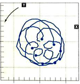
Instability Plot
These conditions produce sub-synchronous vibration with circular shaft orbits. These instabilities are a result of the rotor running on the modified natural frequency of the system.
Thrust Overload
Process upsets, recycle valve malfunction, or fouled internals can increase axial thrust beyond bearing design limits. Excess thrust can rapidly damage thrust bearings, and if the thrust bearing is damaged, that can result in catastrophic loss to the entire machine. Thrust failure are usually detrimental to the machine.
Blade Pass and Aerodynamic Effects
Blade pass frequency (BPF) and harmonics may indicate flow disturbances, surge, stall, or internal damage.
Shaft Crack
A propagating crack reduces rotor stiffness and alters resonant frequency. Changes in the slow roll vector on shutdown could be indicative of a shaft crack. Changes in 1X and or 2X amplitude and phase behavior during startup or coastdown may indicate early crack development. Changes in 1X and or 2X amplitude and phase during steady state operations may indicate that a crack is propagating in the rotor.
Turbine Driver Malfunctions
Turbines can have the same malfunctions as a compressor like Unbalance, Misalignment, Rotor to Stator Rubs, Fluid Induced Instability and Shaft Cracks. In addition to these compressor issues, turbine drivers introduce their own failure modes:
- Steam or gas imbalance
- Nozzle damage
- Coupling defects
- Torsional vibration
- Overspeed events
Monitoring both driver and driven equipment as an integrated system is critical.
Instrumentation
Instrumentation provides early detection of mechanical, aerodynamic, and process-related faults through vibration, position, temperature, and speed monitoring.
Radial Vibration – Proximity Probes
Measure shaft dynamic motion relative to bearings. We recommend two proximity probes mounted in an XY fashion monitoring each bearing. These probes provide orbit plots, phase angle, frequency and amplitude data. This information is essential for detecting all rotor related malfunctions.
The Radial Vibration Probes mounted in an XY fashion also can provide the necessary data to know the shaft position within the bearing clearance. Shaft Centerline Plots are very useful for determining bearing wear and alignment condition.
Axial Position (Thrust) Probes
We recommend continuously monitoring thrust bearing position using two proximity probes. Continuously monitoring thrust bearing position is essential to ensure that the machine stays in a healthy condition. Two probes are used to monitor thrust usually in a dual voting relationship. This helps to prevent against false trips, and to ensure that if you have a trip it is necessary. Thrust monitoring is critical for detecting thrust overload or bearing wear.
Phase Reference (Once Per Turn Marker)
A phase trigger provides rotational reference for phase analysis, typically used in numerous plots, like Bode, polar, full cascade, orbit, time based, full spectrum and overspeed protection integration.
Case Vibration Sensors (Velocity/Acceleration)
Casing mounted seismic sensors are useful for monitoring casing vibration response and structural vibration. If the running speed of the machine is 60 Hz or less, using a velocity sensor is usually the better choice. For higher speed machines an accelerometer should be used.
Temperature Sensors
Monitoring bearing metal temperature and lube oil temperature is essential to understand the health of the machine. Excessive bearing metal temperature can be a result of misalignment, abnormal loading or inadequate lubrication. High lube oil temperature can result in the lube oil losing its effectiveness to properly lubricate the bearings. Monitoring temperature, along with vibration and position information, helps to provide a complete picture of machine condition.
Speed and Overspeed Monitoring
Critical for turbine protection and startup sequencing. Depending upon the nature of the machine, advanced speed detection systems may be required. In some machines, when load is removed suddenly, the speed detection system has to be able to detect the acceleration within a turn of the rotor to prevent an overspeed failure.
Process Parameter Integration
- Suction/discharge pressure
- Flow rate
- Temperature
- Valve position
- Suction Tank Level
Modern systems integrate these signals into predictive analytics platforms to detect deviations and trend machine health over time.
Critical Turbine Driven Compressor Monitoring
Due to the critical nature of these machines, Metrix recommends:
- XY proximity probes at each radial bearing
- Dual axial thrust position sensors
- Phase trigger for speed and phase reference
- Bearing metal temperature sensors
- Case vibration sensors (as required)
A typical four (4) bearing turbine compressor train requires:
- 8 XY Radial Vibration Sensors (Proximity)
- 2 Axial Thrust Position Sensors
- 1 Phase Reference Sensor
- 4–8 Bearing Temperature Sensors
- 2–4 Casing Vibration Sensors
This configuration aligns with API 670 machinery protection standards and provides excellent rotor dynamic visibility.
The MX5000 Monitoring Platform
The MX5000 is ideally suited for turbine driven compressor applications.
Sensor Interface Module (SIM)
The four-channel monitor is capable of vibration, position, speed and 4-20 mA inputs. Modules can be combined to create a 24-channel protection system.
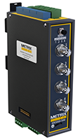
A Sensor Interface Module
A single SIM is a monitoring system in and of itself. It can stand alone. Each SIM has 4 solid state relays, Modbus output, 4-20 mA outputs, as well as dynamic outputs that can be sent 300 meters without signal degradation.
Rack Emulation Module (REM)
Provides API 670-compliant rack functionality, including:
- Mechanical relays (4)
- Contacts for:
- Rack bypass
- System Reset
- Trip multiply
- NOT OK
- Monitoring System Status
- TCP/IP Communications
Temperature Interface Module (TIM)
Eight-channel temperature monitor that integrates with SIM and REM modules to provide a complete turbomachinery protection system. Each TIM can stand alone or can be combined into a 56 channel temperature monitoring system. The TIM can accept thermocouples or resistance temperature detectors.
Each module provides:
- 4–20 mA outputs for each channel
- 4 Solid-state relays
- RS485 Modbus communications
- Integration into plant DCS or asset management systems
The MX5000 architecture allows flexible configuration for small compressor packages or large critical compressor trains.
Case History
Gas Processing Facility Example
A 12,000 HP gas turbine driven centrifugal compressor experienced increasing sub-synchronous vibration during seasonal load changes.
Orbit plots revealed forward precession at approximately 0.4× running speed — indicative of oil whirl. Bode plots showed phase instability near the first critical speed.
Corrective action included:
- Bearing clearance verification
- Lube oil pressure adjustment
- Installation of modified bearing geometry
Early detection prevented rotor contact and avoided a potential multi-million-dollar outage.
Estimated avoided downtime:
3 days at $250,000 per day in lost profitability = $750,000.
LNG Facility Example
A thrust position alarm activated during startup. Trending data showed gradual axial movement correlated with increasing discharge pressure.
Root cause: recycle valve malfunction causing excessive thrust load.
Corrective action prevented thrust bearing failure and avoided catastrophic compressor damage.
Pipeline Compressor Station Example
A mainline compressor failure can reduce gas throughput, leading to contractual penalties worth tens of thousands of dollars per hour. Continuous monitoring ensures rapid detection of instability, unbalance, or thrust overload before forced shutdown occurs.
Return on Investment
Assuming predictive monitoring prevents even one major outage within three years, the investment in machinery protection and condition monitoring instrumentation typically pays for itself after the first avoided incident.
Benefits include:
- Reduced unscheduled downtime
- Improved personnel safety
- Compliance with API standards
- Extended equipment life
- Lower maintenance costs
- Increased operational confidence
For the four (4) bearing turbine compressor train discussed earlier, the required MX5000 Monitoring System would include:
- One Rack Emulation Module (REM)
- Three Sensor Interface Modules (SIM)
- One Temperature Interface Module (TIM)
(Additional modules available depending on channel requirements.)
Conclusion
Turbine driven compressors are high-energy, high-risk rotating assets where failure can result in catastrophic equipment damage, extended downtime, and significant financial loss.
The MX5000 provides a flexible, API-aligned, and scalable monitoring solution that delivers real-time machinery protection and actionable condition monitoring data — ensuring reliability, safety, and profitability.
Turbine Driven Compressor
Minimal Recommended Sensor Suite:
- 8 XY Radial Vibration Sensors (Proximity)
- 2 Axial Thrust Sensors (Proximity)
- 1 Phase Trigger Sensor (Proximity)
- 4 Temperature Sensors (TC or RTD)
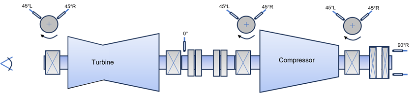
Turbine Driven Compressor
MX5000 Includes:
- One Rack Emulation Module (REM)
- Three Sensor Interface Modules (SIM)
- One Temperature Interface Module (TIM)