Metrix Vibration's Glossary
Vibration Glossary
A | B | C | D | E | F | G | H | I | L | M | N | O | P | R | S | T | U | V | W | X | Z
- 4-20mA Signal (4-20mA Current Loop): A 4-20mA current loop is an analog electronic signaling approach in which a two-wire transmitter device sets current in a range of 4 to 20mA to a value that is proportional to a signal of interest. Widely used in industrial control applications, the approach offers an advantage that accuracy is not affected by a voltage drop due to electrical resistance in the wiring. Additionally, it can provide operating power to the connected transmitter. For more information click here.
A
- Absolute Phase: The timing relationship measured in degrees between a once-per¬turn shaft marker followed by the first vibration peak of a filtered vibration signal. The angle between the once-per-turn shaft marker and the first positive peak of the filtered vibration signal is measured between zero (0) and 360 degrees lagging (lagging because it is always measured after the once per turn marker). It is called “Absolute” because it only occurs when the shaft marker (key way or projection) is aligned with the probe or pickup (see Once-per-turn market below) followed by the positive peak in the filtered vibration signal.
- Accelerometer: A transducer that converts mechanical acceleration into an electronic signal. It is a seismic sensor made from a piezoelectric material which produces a charge output proportional to acceleration (pC/g). When housed together with an electronic charge amplifier and charge-to-voltage converter (mV/g), it is referred to as an "internally amplified" accelerometer. If, due to temperature, only the sensor is machine mounted, the remote electronics are referred to as a "charge amplifier" (although it usually also contains a charge-to-voltage convertor). See Accelerometers
- Accelerometer Frequency Response: Accelerometer frequency response is a specification of the accelerometer sensitivity as a function of frequency.
- Accelerometer Sensitivity: Accelerometer sensitivity is a specification of the ratio of the accelerometer's mechanical input to electrical output typically specified at a 100-Hz reference frequency or, as in the case of Accelerometer Frequency Response, as a function of a range of frequencies.
-
Amplitude: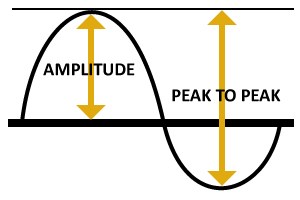
Amplitude is a measure of the change of a signal value as a function of time. "Peak-to-peak amplitude" referes to the change between minimum and maximum values of a signal. "RMS Amplitude" refers to Root Mean Square amplitude which is the square root of the mean of a signal.
-
Axial (Thrust) Position: Change in (or average) position of a rotor in the axial direction with respect to a thrust bearing support structure or nearby fixed point. A proximity probe observes the shaft, its thrust collar or other nearby integral axial shaft surface. Measurement is made by a known probe gap distance (voltage) representing a known position of the thrust collar relative to the thrust bearing clearance.
B
- Balance-of-Plant Machines: Those that are not critical to the overall plant process. They often operate in tandem or spared installations.
- Balancing: Procedure for adjusting the radial mass distribution of a rotor so that the mass centerline (principal inertia axis) approaches the rotor rotational axis. This reduces the radial vibration of the rotor due to unbalanced inertia forces and the forces on the bearings at the once-per-revolution frequency.
C
- Calibration: Test where known values of the measured variable are applied to a sensor, signal conditioner, monitor or the entire channel output readings to verify or adjust as necessary.
- Channel: A sensor with the associated signal conditioner and monitor hardware required to display its output signal.
- Condition Monitoring: A broad field of measurement and analysis of machine parameters to determine machinery health. Modern condition monitoring programs supplement real-time catastrophic vibration, temperature and process "protection monitoring" with more complex often computer based "predictive" maintenance analysis tools. Their aim is to predict the potential timing of machinery failures relative to scheduled production rather than potentially unnecessary time interval-based "preventative" maintenance. Supplemental tools may include performing vibration analysis, oil analysis, laser alignments and automated balancing. The use of thermography for undesirable heat transfer due to coupling misalignment, process or electrical connection problems, and the monitoring of acoustic changes in certain valves and rolling element bearings are also employed.
- Critical Machines: Critical machines are those required for a major part of the plant. When they go down, that part of the process cannot operate. They are usually unspared and monitored continuously.
- Cross Axis (Transverse) Sensitivity: Ratio of the change in signal output of a seismic sensor to an incremental change to a stimulus along any axis perpendicular to the sensitive axis.
- Cross Talk: Interference or noise in a sensor or channel which has its origin in another sensor or channel. It may occur when two (or more) proximity probe tips are too close together, resulting in the interaction of their electro-magnetic fields. The result is to have one signal component on each sensor's output signal. The frequency of the noise is the difference (beat frequency) of the two probe driver oscillation frequencies.
D
- Digital Proximity System: The DPS consists of a proximity probe, an extension cable, and a signal conditioner. Two models are available for the signal conditioner depending on the required signal output format: the MX2033 3-Wire Driver and the MX2034 4-20 mA Transmitter. You can reconfigure these flexible devices to handle a variety of probe and cable combinations from Metrix as well as Bently Nevada and other competitors. Learn more here.
- Displacement: The change in distance, or position, of an object. It is usually a peak-to-peak measurement of vibration with units of mils or microns. In proximity monitoring, eddy current proximity probes measure shaft displacement directly. In seismic monitoring, integration of a velocity sensor signal is necessary to obtain displacement. An acceleration signal requires double (two stage) integration to yield a displacement measurement.
- Dual Path: Technique used in signal conditioners and/or monitors whereby a single sensor input is processed through two separate paths; each has its’ own measurement units (e.g., velocity and displacement), optional filtering, setpoints and readout displays.
- Dual Voting: A concept requiring that two independent inputs agree before action is taken. This function may be incorporated in a monitor, whereby two (vs. only one) sensor input signals must both measure an amplitude value which exceeds a set point (usually the Danger set point only) before an alarm condition is indicated.
- Dynamic Motion: Vibration of a rotor system.
E
- Eddy Current: Electrical current generated (and dissipated) in a conductive material (usually a rotor shaft) when it intercepts the electro-magnetic field of a proximity probe.
- Electrical Runout: A source of signal error from a proximity sensor system which repeats with each shaft revolution; A probe driver output signal change not resulting from a probe gap change (dynamic motion or change in position); Often caused by varying conductivity of the shaft material or the presence of localized magnetic fields at a point(s) on a shaft surface. See also Mechanical Runout.
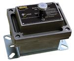
- Electronic Vibration Switch: Unitization of an accelerometer, signal conditioner and monitor (i.e. single seismic monitoring channel). Offers setpoint time delay(s) for false trip avoidance and more sensitive velocity (or displacement) measurement. Most have an optional second setpoint. See Electronic Vibration Switch.
- Error: Difference between the indicated and true values of the measured variable. Typically expressed as relative error which is a percentage of the output reading of the sensor.
- Essential Machinery: Then one critical to part of the plant. When down, the overall plant cannot operate to full capacity. They can be spared or unspared and are usually monitored continuously.
- Extension Cable: A coaxial cable used to connect a proximity probe’s cable to a probe driver. It serves to 1) extend the distance to a suitable location for a probe driver and 2) provide a disconnect point for easier installation and removal of standard mount style, threaded proximity probes. See also System Length.
F
- Filter: Implementable digitally in software or with analog circuitry, filters are elements that pass or rejects a frequency band usually to isolate a particular machinery mechanical condition(s). “High pass” filters allow only frequencies higher than their design frequency to pass (i.e. be detected). “Low pass” filters permit only lower ones. “Band pass filters” are both low and high pass to narrow both ends of a standard frequency response range. At a filter’s design frequency, amplitude signal attenuation is usually -3 dB and then slopes off (attenuates further) beyond at the design “roll off rate”.
- Forced Vibration: Forced vibration is the oscillation of a system under the action of a forcing function usually occurring at the frequency of the excitation force.
- Free Vibration: Vibration of a mechanical system following an initial perturbation (change of position or velocity). Depending on the kind of perturbation, the system responds by free vibration at one or more of its natural frequencies.
- Frequency: Repetition rate of a periodic vibration within a unit time. Normally expressed in units of cycles per minute (cpm), or cycles per second (cps or Hz) and may be expressed relative to shaft RPM. For rotating machinery vibrations, there are two types of frequencies of interest: 1) the shaft rotational frequency (RPM) and 2) the various vibration frequencies as measured by vibration sensors. Vibration frequencies are usually expressed as a fraction or percentage of the shaft RPM: 1X means one times RPM, 2X means two times, 1/2X, means 50%, etc.
- Frequency Response: It is the measured amplitude and phase characteristics of a mechanical or electronic system with respect to frequency.
G
- g: "Little" g is the value of acceleration yielded by the force of Earth’s gravity, which varies somewhat with the latitude and elevation of the point of observation. A value of 9.81 m/s2 = 386 in/s2 = 32.2 ft/s2 is used for the acceleration due to gravity at sea level. For more information click here.
- Gear Mesh Frequency: Potential vibration frequency on any machine employing gears. It is calculated by multiplying the number of gear teeth times the RPM of that gear shaft. For a given set of gears, all contacting gears have the same gear mesh frequency for normal operation or else they would not mesh and soon fail.
H
- Harmonics: Sinusoidal quantities at frequencies that are an integer multiple of the fundamental frequency.
- Hertz (Hz): Unit of frequency in cycles/ second. Divide shaft RPM by 60 for frequency in Hz.
- Hysteresis (Deadband): Non-uniqueness between two variables as a parameter increases or decreases. In particular, the maximum difference in output at any given value of the measured variable within the specified range, when the value is first approached with an increasing signal and then a decreasing one. Also called deadband, or that portion of a system’s response where a change in input does not produce a change in output.
I
- Inertially Referenced:Inertially referenced motion is referenced to free space or to a fixed point in space; a sensor which measures such motion.
- Integrator: Circuitry used in a seismic signal conditioner and/or monitor which performs mathematical integration. It converts a velocity signal to displacement or an acceleration signal to velocity. A double integrator converts an acceleration signal to displacement.
L
- Linearity: Closeness of a calibration curve to a specific straight line, expressed as the maximum deviation of any calibration point to that line during any one calibration increment.
M
- Mechanical Runout: Source of error on the output of signal of a proximity sensor system; a probe gap change not resulting from a shaft center position change or dynamic motion. Common sources include out-of-round shafts, scratches, chain marks, dents, rust, stencil marks, at spots, and engravings.
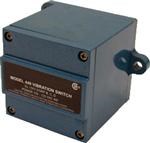
- Mechanical Vibration Switch: Resettable device which, after observance of a forced vibration greater than its setpoint, accelerates a mass (e.g. a lever) to initiate closure or opening of a set of internal field contacts. See Mechanical Vibration Switch.
- Micron (Micrometer): Length or displacement equal to 10^-6 meters. One micron is equal to 0.04 mil.
- Monitor: A loosely used instrumentation term. For machinery, a “protection” monitor may accept inputs from a variety of sensors including temperature, vibration, RPM and 4- 20 mA output types. As a minimum, the monitor compares real-time measured values (after any signal conditioning) to an alarm setpoint(s), various input sensor/wiring integrity and provides for relay output for machinery ALERT and/or DANGER warning. When the accepted monitor inputs include traditional vibration sensors with dynamic output that require the monitor to also have internal signal conditioning, it is referred to as a “vibration input” monitor. When a monitor accepts only 4-20 mA inputs from vibration transmitters (such as a PLC, DCS or certain Metrix products) it is often referred to as a “4-20 mA input” monitor.
N
- Noise: Any component of a sensor output signal that does not represent the variable intended to be measured.
O
- Once-per-turn marker: if using a Proximity Probe it is called a Phase Trigger (BN uses the word Keyphasor due to the fact that a proximity probe usually uses a keyway to generate the once-per-turn pulse). You can also use a magnetic pickup or optical pickup to generate the signal required for the once-per-turn shaft marker.
P
- Peak-to-Peak Value:The difference between positive and negative extreme values of a signal or dynamic motion. See Amplitude.
- Periodic Vibration: Oscillatory motion whose amplitude pattern repeats in time.
- Phase: A measurement of the timing relationship between two signals, or between a specific vibration signal and a once-pershaft revolution event (phase angle).
- Phase Reference Probe: A probe used for 1) determining the unbalance location (phase angle) relative to a measure once-per shaft revolution event location (e.g. a keyway or reflective tape); 2) for complex vibration vector addition or subtraction measurements. The sensor used in phase reference measurements with installed “protection” monitors is usually a proximity sensor system over a keyway. Unprotected machines, or those without a permanent phase reference probe, may have reflective tape temporarily added to be observed by an optical sensor.
- Piezoelectronic: Any material which provides a conversion from mechanical to electrical energy. For a piezoelectric crystal, if mechanical stresses are applied on two opposite faces, electrical charges appear on another pair of faces.
- Probe: Loosely used term for any machine mounted instrument including a vibration sensor. See Probes.
- Proximity Monitoring: One or more channels of monitoring each consisting of: 1) proximity sensor system; 2) signal conditioner; 3) monitor. For a given application, these monitoring components may be partially combined (e.g. a probe driver and a signal conditioner to form a unitized vibration transmitter) or entirely into a proximity switch with relay output.
- Proximity Probe: A non-contacting device which measures the displacement motion and position of an observed surface relative to the probe mounting location. Proximity probes used for rotating machinery measurements usually operate on the eddy current principle and measure shaft displacement motion and position relative to the machine bearing(s) or housing.
- Proximity Probe Driver (Oscillator-Demodulator): A device which sends a radio frequency signal to an eddy current proximity probe usually through an extension cable, demodulates the probe output, and provides output signals proportional to both the average and dynamic probe gap distances.
- Proximity Probe Gap: The physical distance in micrometers or mils between a target (e.g. a machinery shaft or proximity sensor calibrator target) and a proximity probe tip. The measurement is made either mechanically with a “feeler” or thickness gauge or, more commonly due to machinery case access constraints, electrically by a DC output voltage signal reading from a powered proximity sensor system. Setting the probe gap refers to static (i.e. machine off) positioning of the probe to a distance from the shaft in the center of the sensor system’s linear range. This allows for linear electronic measurement of a movement (i.e. machine on) arising from dynamic radial vibration or changes in axial position about this static probe gap provided it does not exceed the sensor system’s maximum linear range in either direction.
- Proximity Probe Orientation: The angular location of a proximity probe with respect to a polar coordinate system when viewed from the driver end of a machine. Usually, zero degrees is at top dead center (vertical) or at the horizontal right (3 o’clock) position on the coordinate system.
- Proximity Sensor Calibrator: A mechanical device which generates dynamic motion of an observed surface at a known amplitude and frequency. The surface is observed by a proximity probe for the purpose of calibrating only the proximity sensor system or, with its monitor, an entire proximity channel.
- Proximity Sensor System: An electrically matched (tuned) sensor system comprised of a proximity probe, usually an extension cable and a probe driver.
R
- Radial:A direction of a machine which is perpendicular to the shaft centerline; in the XY plane; usually refers to direction of shaft or casing motion or measurement.
- Radial (Centerline) Position: The average position of the shaft centerline within the bearing. This can be measured by noting the change in VDC output of two XY probes from a known position with the shaft at rest. The XY probes should be attached to the bearing or its’ housing to eliminate thermal growth errors.
- Radial (Lateral) Position: Shaft dynamic motion or casing vibration which is measured at 90o to the shaft centerline.
- Relative Motion Vibration: measured relative to a chosen reference. Proximity probes measure shaft dynamic motion and position relative to the probe mounting, usually the bearing or bearing housing.
- Relative Phase: The timing relationship measured in degrees between two like vibration signals (velocity to velocity, acceleration to acceleration, displacement to displacement – not velocity to displacement or acceleration to velocity) measured between zero (0) and 180 degrees leading or lagging.
- Relative Probe: A proximity probe observing shaft motion relative to a stationary reference such as a bearing housing.
- Repeatability: The ability of a sensor or monitor to reproduce output readings when the same value is applied to it repeatedly, under the same conditions, and in the same direction. Also the maximum deviation from the mean of corresponding data points taken from repeated tests under identical conditions.
- Resistance Temperature Detector (RTD): A sensor which measures temperature or temperature change as a function of resistance.
- Resolution: The smallest change in applied stimulus that will produce a detectable change in the instrument output. Resolution differs from precision in that it is a psycho-physical term referring to the smallest increment of humanly perceptible output (rated in terms of the corresponding increment of input).
- Resonance: The condition where a forcing frequency coincides with a natural frequency of the system. A resonant condition usually causes a substantial amplitude increase.
- RMS (ROOT MEAN SQUARE): Square root of the arithmetic average of a set of squared instantaneous values. In rolling element bearings, certain bearing problems may be indicated by increased RMS vibration levels of the outer race motion. See Amplitude.

- Rolling Element Bearing: A bearing which uses rolling elements (rollers or balls) to support the load of a rotating shaft with minimum friction.
- Ryton:A highly chemical and abrasion resistant polymer (polyphenylene sulfide resin) made by Chevron Phillips Petroleum Company used to fabricate proximity probe tips. For more information click here.
S
- Seismic Monitoring: One or more channels of monitoring each consisting of: 1) seismic (casing) accelerometer or velocity sensor; 2) signal conditioner; 3) monitor. For a given application, these monitoring components may be partially combined (e.g. an accelerometer and a signal conditioner to form a unitized vibration transmitter) or entirely into an electronic vibration switch with relay output.
-
Sensor: A device for translating the magnitude of one quantity to another. The second quantity often has different units of measure and serves to provide a more useful signal. Vibration sensors convert mechanical motion into an electronic (typically a voltage proportional) signal.
See sensors.
- Set Point (Trip) Multiplier: A function provided in a monitor system to temporarily increase the alarm (Alert and Danger) setpoint values by a specific multiple (usually two or three). This function may be applied by manual or control relay action during start-up to allow a machine to pass through high vibration speed ranges without excessive monitor alarm indications. Such speed ranges may include system resonances and other normal transient vibrations.
- Setpoint: An adjustable threshold above which a measured value will initiate relay output indicating a machine or process Alert and/or Danger warning condition.
- Signal Attenuation: The reduction in magnitude of a signal without changing the basic characteristics of the signal. Also, the amount of voltage reduction utilized to reduce large electronic signals down to full scale deviation on instruments such as tape recorders. This non-dimensional number is usually in even steps of 0.5, 0.2 and 0.1 Signal attenuation may also result from reduced mechanical transmission of vibration from one machine part to another (e.g., shaft to bearing housing) and also from signal conditioner circuits in some applications.
- Signal Conditioner: A device placed between a signal source (sensor) and a monitor to change the signal. Examples: attenuators, amplifiers, signal converters (for changing one electrical quantity into another such as volts to amps, analog to digital, integrators) and filters.
- Signal Gain: The change in magnitude of a signal. Also, the voltage amplification utilized to enlarge small electronic signals up to full scale deviation on instruments. Often expressed in steps of 2, 5, and 10.
- Ski-Slope: An elevated noise floor that decreases with increasing frequency, often overwhelming the peaks at discrete frequencies that are present in normal measurements.
- Spall: A flake or chip of metal removed from one of the races from a rolling element of a bearing. Spalling is evidence of serious bearing degradation and may be detected by relatively small increases in signal amplitude at the bearing frequencies during operation.
-
System Length: A feature of proximity sensor systems equal in magnitude to the combined electrical lengths of a proximity probe and (usually) an extension cable are matched (tuned) to the proximity probe driver electronics for proper function (linearity). Newer proximity sensor systems generally have 5 or 9 m system lengths that are normally within +/-5% of their dimensional length. Some older systems have 15 or 20 feet system lengths and, for small diameter probes, have up to -15% shorter dimensional lengths.
T
- Thermistor:An electrical device used for temperature measurement. Their coefficients of resistance are either positive or negative (i.e., with increasing temperature, the resistance may increase or decrease for a given type).
- Thermocouple: A temperature sensing device comprised of two dissimilar metal wires which when thermally affected (heated or cooled) produce a proportional change in electrical potential at the point where they join.
- Threshold: The smallest change in the measured variable that will result in a measurable change in an output signal.
Thrust Position See Axial Position.
- Time Delay: Electronic vibration protection systems usually offer two types to avoid false alarms for transient conditions: 1) machine start up time delay (or setpoint multiplication); 2) monitor (running) time delay. They may be of fixed or adjustable time duration.
- Total Runout: Equal in magnitude to the electrical plus the mechanical runout.
- Transducer: See Sensor.
- Transient Vibration: Temporary vibration of a mechanical system. It may consist of forced or free vibration or both. Transient vibration is typically associated with changes in machine operating condition such as speed, load, etc.
- Turbine Supervisory Instrumentation (TSI): A TSI system is a continuous monitoring system generally used on turbogenerator sets. It can include such measurements as shaft radial vibration, shaft absolute vibration, axial thrust position, differential expansion case expansion, valve position, eccentricity peak-to-peak, zero speed, and shaft RPM. Metrix does not currently offer this type of instrumentation.
U
- Unbalance (Imbalance): Unequal radial weight distribution on a rotor system; a shaft condition where the mass centerline (principal inertial axis) does not coincide with the geometric centerline. Also, the amount of mass causing the unbalance.
V
-
Velocity: Time rate of change of displacement. Velocity leads displacement by 90 degrees in time. Units for velocity are inches/second or millimeters/second, zero-to-peak or RMS. Velocity measurements are obtained 1) by electronic integration of an acceleration signal from an accelerometer or 2) directly from a velocity sensor. Velocity is a widely used measurement for evaluating machine casing and other structural response characteristics.
- Velocity Sensor: A seismic sensor which converts velocity motion into a proportional electrical signal.
- Velocity Transmitter: A velocity transmitter produces a 4-20mA signal proportional to axial velocity.
- Vibration: Dynamic motion resulting from an applied stimulus. Out-of-tolerance measurements for excessive vibration are useful to protect from 1) personnel injury; 2) costly machinery downtime; 3) avoidable extensive repairs; 4) higher insurance rates.
- Vibration Analysis and Data Collection: Process involving the collection, manipulation, display and more specifically the interpretation of machine casing and/or shaft vibration waveform as it relates to machine condition. Except for the very largest machines, data collection is commonly done by walk around operators who are properly trained in collecting scheduled measurement points. Permanently mounted proximity or seismic sensors that are of part of an excessive vibration “protection” monitor are accessed when possible, or an accelerometer is temporarily attached for casing measurements. Depending on the data collector, the data may be displayed by an on board screen or downloaded, stored and later retrieved for manipulation on a PC prior to analysis. Root cause of high or increasing vibration is performed by analyzing both time waveforms, frequency spectrums (i.e. amplitudes at discrete frequencies) for a given instance in time and phase information.
- Vibration Meter: A portable one or two part (remote sensor) instrument used to measure seismic (casing) vibration amplitude.
- Vibration Transmitter: An instrument combining a seismic accelerometer or a proximity probe driver vibration sensor together with a voltage-to-current signal conditioner to provide proportional 4-20 mA output. This output represents the zero to full scale nameplate vibration and provides an input to a user’s PLC or DCS wherein a setpoint(s), time delay(s) and input integrity check(s) may be programmed as part of the monitor function.
W
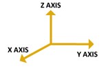
- XY: Perpendicular axes in a Cartesian coordinate system. Usually used as a reference for orthogonal mutually perpendicular dual vibration sensors.
Z
- Zero-to-Peak Value: One half of the peak-to-peak value.